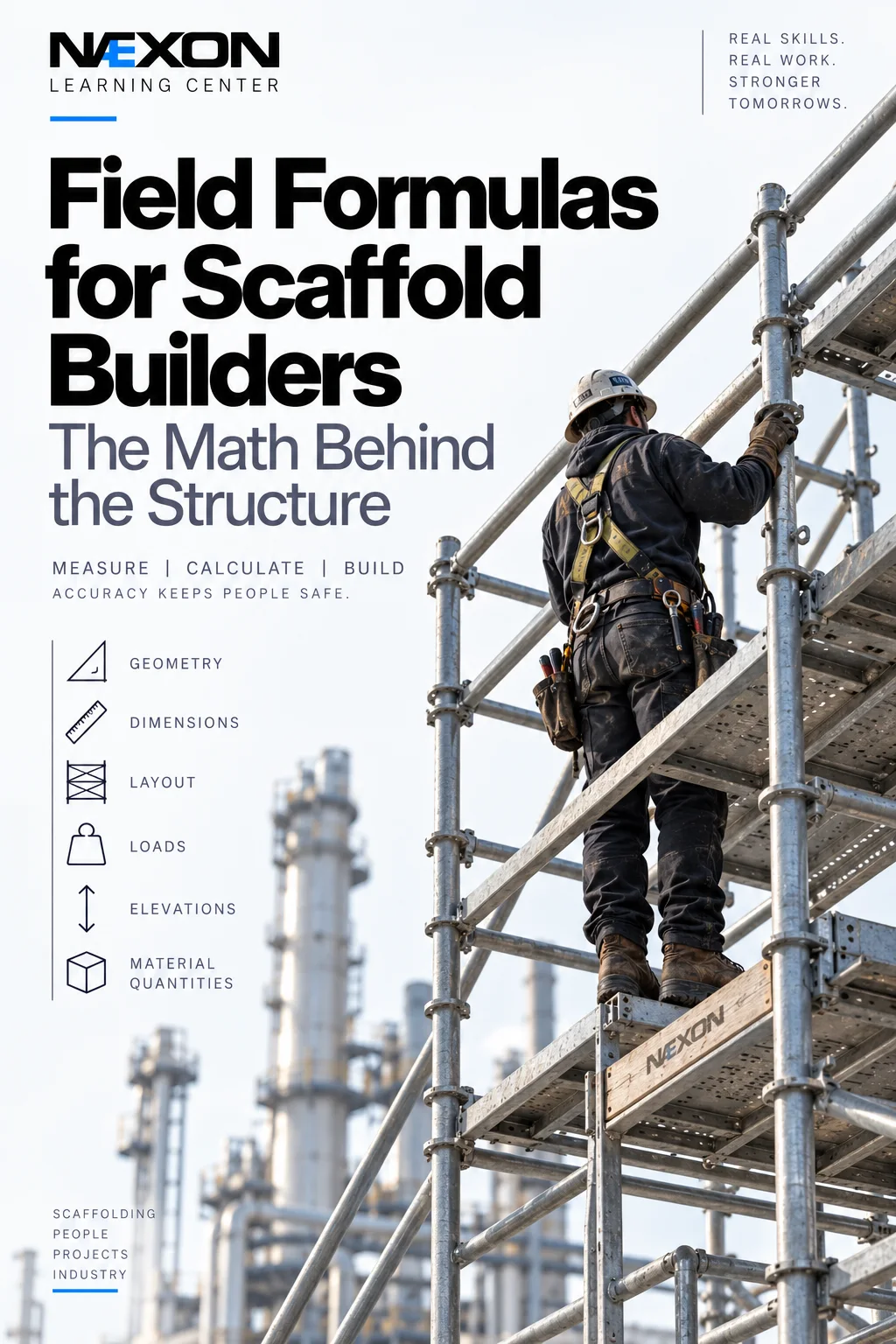
Scaffold building is not just assembling frames, tubes, boards, and braces. Every scaffold depends on geometry, dimensions, elevations, loads, spacing, and level.
A scaffold can look simple from the ground while containing dozens of mathematical relationships. Bay length, lift height, diagonal measurements, platform area, load distribution, slope, bracing angles, and material quantities all have to work together.
Understanding the math helps scaffold builders lay out structures accurately, recognize geometry problems early, estimate materials, and understand how dimensions interact.
These formulas are practical learning references. Scaffold design drawings, manufacturer instructions, engineered scaffold plans, competent-person requirements, applicable regulations, site procedures, and load restrictions always control the actual scaffold.
1. Squaring a Scaffold
The Pythagorean theorem is one of the most useful formulas for scaffold layout:
A² + B² = C²
Therefore:
C = √(A² + B²)
Where:
A = length
B = width
C = diagonal
Example
A scaffold footprint measures:
12 ft × 16 ft
The theoretical diagonal is:
C = √(12² + 16²)
= √400
= 20 ft
Checking the corresponding diagonals helps verify that a rectangular scaffold layout is square.
2. The 3-4-5 Rule
A quick field method for establishing a 90° corner is the:
3-4-5 triangle
Because:
3² + 4² = 5²
The relationship can be scaled:
6-8-10
9-12-15
12-16-20
Example
Measure:
12 ft along one direction.
Measure:
16 ft along the perpendicular direction.
Adjust the corner until the diagonal measures:
20 ft
You now have the geometry of a 90° corner.
3. Finding a Diagonal
When the horizontal and vertical dimensions are known:
Diagonal = √(Length² + Height²)
Example
A brace spans:
8 ft horizontally
and:
6 ft vertically
Diagonal = √(8² + 6²)
= √100
= 10 ft
This relationship helps explain the geometry behind diagonal braces.
Actual brace selection and installation must follow the scaffold system’s approved configuration.
4. Finding the Brace Angle
When rise and run are known:
θ = arctan(Rise ÷ Run)
Example
Rise:
6 ft
Run:
8 ft
θ = arctan(6 ÷ 8)
≈ 36.87°
This gives the theoretical angle of the diagonal from horizontal.
The same triangle gives:
Brace Length = 10 ft
So one set of measurements tells you both the diagonal length and its angle.
5. Scaffold Height
Total scaffold height can be estimated from:
Total Height = Number of Lifts × Lift Height
Example
A scaffold has:
6 lifts
Each lift is:
6 ft 6 in
Convert:
6 ft 6 in = 6.5 ft
Then:
6 × 6.5
= 39 ft
This gives the basic vertical height represented by those six equal lift intervals. Actual overall scaffold height depends on the system configuration and how the project defines lift and total height.
6. Total Scaffold Length
For equal bays:
Total Length = Number of Bays × Bay Length
Example
Eight bays:
8 ft each
Total Length = 8 × 8
= 64 ft
If bay sizes vary, calculate them individually:
Total Length = Bay₁ + Bay₂ + Bay₃ + …
This is useful for planning scaffold runs around equipment, pipe racks, vessels, structures, and buildings.
7. Platform Area
Platform area is:
Area = Length × Width
Example
A working platform measures:
24 ft × 5 ft
Area = 24 × 5
= 120 ft²
Platform area can help with material planning and understanding the size of a working level.
It does not, by itself, determine allowable scaffold loading.
8. Scaffold Face Area
For a rectangular scaffold face:
Face Area = Length × Height
Example
Length:
40 ft
Height:
30 ft
Face Area = 40 × 30
= 1,200 ft²
Face area becomes particularly important when considering containment, sheeting, debris netting, or other materials that can interact with wind.
Wind-related scaffold design must be handled according to the applicable engineered and site requirements.
9. Load Per Square Foot
A simplified average distributed load can be expressed as:
Average Load = Total Load ÷ Platform Area
Example
Total distributed load:
2,400 lb
Platform area:
120 ft²
2,400 ÷ 120
= 20 psf
This only describes an average mathematical distribution.
Actual scaffold loading can include concentrated loads, workers, tools, stored material, equipment, impact effects, and unequal load paths.
Never use a simple average-load calculation to establish scaffold capacity.
10. Load Per Bay
For a simplified case where a uniformly distributed load is divided equally among identical bays:
Average Load per Bay = Total Uniform Load ÷ Number of Bays
Example
Uniform load:
4,800 lb
Number of equal bays:
6
4,800 ÷ 6
= 800 lb per bay
This is a mathematical average only.
Actual forces through standards, ledgers, transoms, bearers, decks, connections, and foundations depend on the scaffold system and loading arrangement.
11. Percentage Grade
When scaffold foundations or surrounding surfaces change elevation:
Grade % = Rise ÷ Run × 100
Example
Rise:
6 in
Run:
20 ft
Convert 20 ft to inches:
20 × 12 = 240 in
Then:
Grade % = 6 ÷ 240 × 100
= 2.5%
This calculation describes the slope of the surface.
It does not determine whether the surface or scaffold configuration is acceptable.
12. Finding Rise From Grade
The grade formula can be rearranged:
Rise = Run × Grade % ÷ 100
Example
Run:
30 ft
Grade:
2%
Rise = 30 × 2 ÷ 100
= 0.6 ft
Convert to inches:
0.6 × 12
= 7.2 in
The elevation changes approximately:
7.2 inches over 30 feet
13. Elevation Difference
To determine vertical change between two elevations:
Elevation Difference = Final Elevation − Starting Elevation
Example
Starting elevation:
EL 100’-0”
Working elevation:
EL 128’-6”
Difference:
28’-6”
This can help establish scaffold platform locations relative to structural or equipment elevations.
Always verify the datum being used.
14. Number of Bays Required
For a required scaffold length:
Number of Bays = Required Length ÷ Bay Length
When the answer is not a whole number, the layout generally requires another bay or a different approved bay arrangement.
Example
Required coverage:
50 ft
Standard bay:
8 ft
50 ÷ 8
= 6.25
Six 8-ft bays provide only:
48 ft
Seven provide:
56 ft
The actual configuration must be selected according to the scaffold system, site geometry, and approved plan.
15. Number of Lifts Required
A similar relationship can estimate vertical layout:
Number of Lift Intervals = Required Height ÷ Lift Height
Example
Required vertical coverage:
42 ft
Nominal lift height:
6 ft
42 ÷ 6
= 7
So the geometry contains:
7 lift intervals
Actual scaffold configuration, top working level, guardrails, standards, and other components must be determined from the approved system and plan.
16. Material Quantity
For repetitive scaffold components, basic quantity estimating can start with:
Quantity = Components per Bay × Number of Bays
Example
If a particular approved layout uses:
2 identical components per bay
across:
10 bays
then:
2 × 10
= 20 components
But real scaffolds often share standards between adjacent bays, contain returns, corners, offsets, additional bracing, ties, access bays, loading bays, cantilevers, and other special conditions.
That means simple multiplication is only the beginning of a material takeoff.
The Diagonal Trap
A scaffold can have the correct overall length and width and still be out of square.
Suppose a rectangular footprint should measure:
12 ft × 16 ft
The theoretical diagonal is:
20 ft
If one diagonal measures:
20 ft
and the opposite diagonal measures:
20 ft 2 in
the layout is not matching the intended rectangular geometry.
The sides may appear correct.
The corner may look close.
But the diagonals expose the problem.
This is why experienced builders verify geometry instead of relying only on appearance.
The Load Trap
Suppose a platform contains:
2,000 lb
spread over:
100 ft²
The simple average is:
20 psf
That does not mean every part of the scaffold experiences exactly 20 lb on every square foot.
If a large portion of that material is stacked in one location, the loading becomes concentrated.
The overall weight did not change.
The platform area did not change.
But the actual load distribution did.
That distinction is critical.
Average load is not the same as allowable load or actual component loading.
Common Scaffold Math Mistakes
Common mistakes include:
- Checking length and width but never checking diagonals.
- Mixing feet and inches.
- Confusing bay count with standard count.
- Confusing lift count with overall scaffold height.
- Assuming every bay is the same length.
- Using platform area as proof of load capacity.
- Treating concentrated loads as uniformly distributed loads.
- Ignoring elevation changes at the foundation.
- Measuring from the wrong structural reference.
- Rounding dimensions too early.
- Forgetting returns, offsets, access bays, or loading bays during material takeoff.
- Assuming more scaffold automatically means greater capacity.
- Ignoring the effects of sheeting or containment.
- Using field math as a substitute for an engineered scaffold design.
Field Rules
Square the base.
Errors established at the bottom can continue through the entire scaffold.
Check diagonals.
A rectangular layout should agree with its intended geometry.
Establish elevations early.
Know where the working platforms need to land before building upward.
Know the difference between bays and lifts.
Bays describe the horizontal layout. Lifts describe vertical intervals.
Keep units consistent.
Convert feet and inches before performing calculations that require common units.
Never calculate your own scaffold capacity from a few simple formulas.
Use manufacturer data, engineered information, applicable requirements, and the approved scaffold plan.
Watch concentrated loads.
A pile of material in one location is not the same as the same weight evenly distributed.
Containment changes the structure’s exposure.
Sheeting and similar materials can introduce significant wind-related considerations requiring proper design.
The scaffold plan controls.
Field math helps builders understand and verify geometry. It does not replace competent engineering or approved system requirements.
Knowledge Check
1. A scaffold footprint measures 9 ft × 12 ft. What is the theoretical diagonal?
15 ft
2. A brace has a 6-ft rise and 8-ft run. What is its theoretical length?
10 ft
3. Eight 7-ft bays create what total nominal run?
56 ft
4. A platform measures 20 ft × 5 ft. What is its area?
100 ft²
5. A surface rises 3 in over a 10-ft run. What is the grade?
Convert:
10 ft = 120 in
Then:
3 ÷ 120 × 100
= 2.5%
6. Does average psf establish allowable scaffold capacity?
No.
Allowable loading comes from the applicable scaffold design and requirements.
Practical Exercise
A scaffold needs to cover a structure approximately:
32 ft long
and:
24 ft high
The proposed layout uses:
8-ft bays
and:
6-ft lift intervals
Horizontal Layout
32 ÷ 8 = 4 bays
The nominal scaffold run is:
4 × 8 = 32 ft
Vertical Layout
24 ÷ 6 = 4 lift intervals
Now consider one 8-ft-wide scaffold face spanning the full 24-ft height.
Face area:
8 × 24
= 192 ft²
If containment were installed across that face, the 192 ft² figure describes the geometric area exposed.
It does not calculate wind force or establish whether the scaffold can safely support containment.
Those decisions require the applicable design information.
Field Challenge
A rectangular scaffold base measures:
18 ft × 24 ft
What should the theoretical diagonal be?
Use:
C = √(18² + 24²)
C = √(324 + 576)
C = √900
C = 30 ft
The intended geometry is therefore:
18 ft × 24 ft × 30 ft
If the corresponding diagonals do not agree with the intended geometry, the base should be checked before the scaffold continues upward.
Final Takeaway
Scaffold math is the geometry behind the structure.
Remember:
Square layout → A² + B² = C²
90° layout → 3-4-5
Brace length → √(Rise² + Run²)
Brace angle → arctan(Rise ÷ Run)
Total run → Bays × Bay Length
Platform area → Length × Width
Face area → Length × Height
Grade % → Rise ÷ Run × 100
Elevation difference → Final EL − Starting EL
Material quantities → understand the actual scaffold configuration before counting
And most importantly:
A calculation can verify geometry. It cannot replace an approved scaffold design.
A good scaffold builder knows where every component goes.
A great scaffold builder understands the geometry holding the entire structure together.