Rigging is physical work, but some of the most important decisions made before a load leaves the ground come down to mathematics.
A rigger needs to understand more than the weight stamped on a piece of equipment. Sling angle, center of gravity, pick-point location, load distribution, material weight, and crane capacity can dramatically change what happens once tension comes onto the rigging.
The formulas below are useful for understanding and checking basic rigging geometry in the field. They do not replace an engineered lift plan, manufacturer instructions, applicable regulations, site procedures, or the judgment of a qualified person.
1. Sling Tension on a Two-Leg Bridle
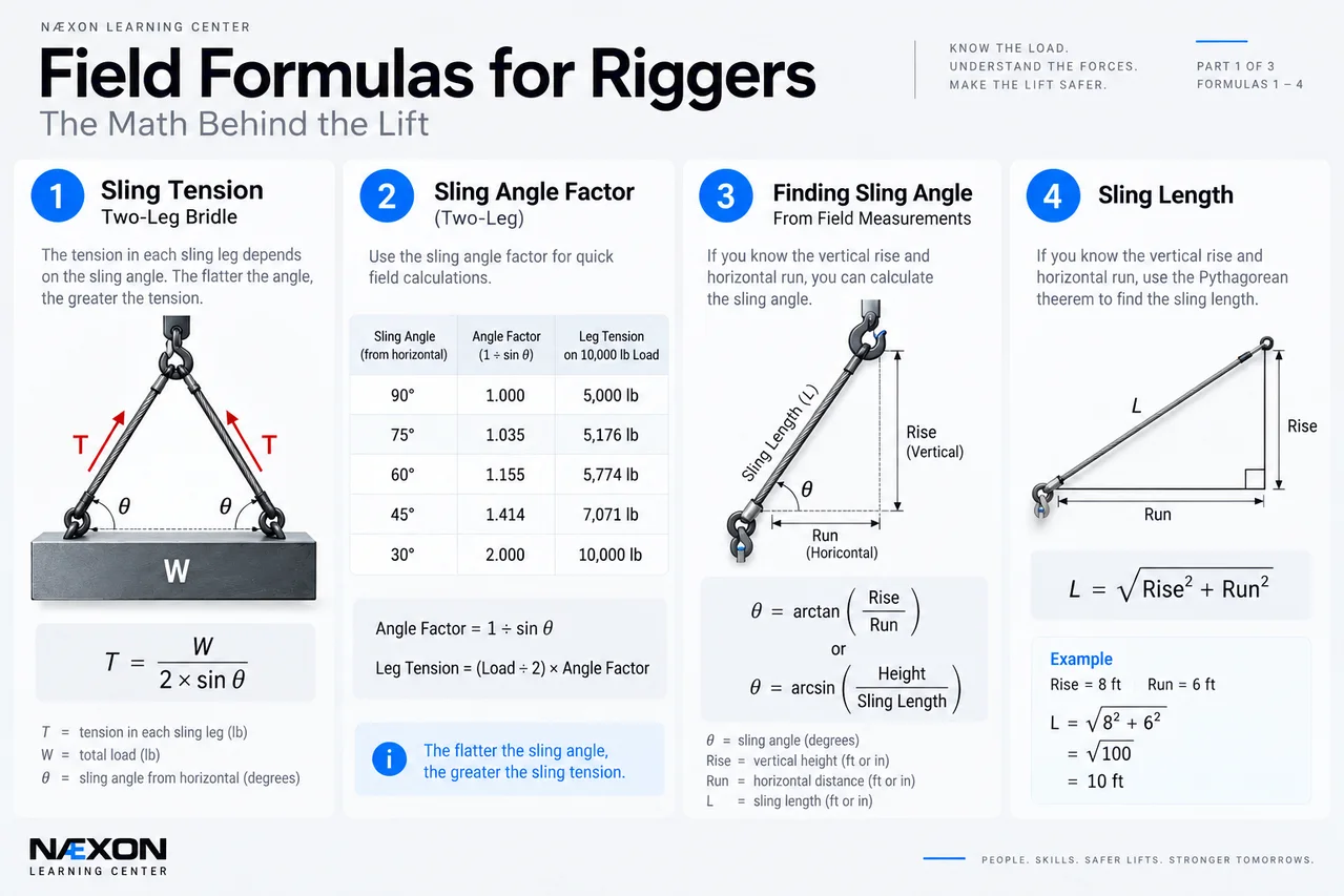
Figure 1. Field Formulas for Riggers — Formulas 1–4: Sling tension, sling-angle factors, finding sling angle from field measurements, and calculating sling length. These relationships show how rigging geometry directly affects the forces acting on a suspended load.
This is one of the most important calculations for a rigger to understand.
When two sling legs support a load symmetrically, each leg does not automatically carry half the load. The tension depends on the sling angle.
When the angle θ is measured from horizontal:
T = W ÷ (2 × sin θ)
Where:
- T = tension in each sling leg
- W = total supported load
- θ = sling angle measured from horizontal
Example
A 10,000-lb load is being lifted with two equally loaded sling legs at 60° from horizontal.
T = 10,000 ÷ (2 × sin 60°)
Since sin 60° ≈ 0.866:
T ≈ 5,774 lb per leg
Although half the load is only 5,000 lb, each sling must actually withstand approximately 5,774 lb of tension.
Reduce the angle and the tension increases rapidly.
2. Sling Angle Factor
A faster field method is to use a sling-angle factor.
Angle Factor = 1 ÷ sin θ
Then:
Leg Tension = (Load ÷ 2) × Angle Factor
For a symmetrical two-leg bridle:
Sling Angle
Angle Factor
Leg Tension on a 10,000-lb Load
90°
1.000
5,000 lb
60°
1.155
5,774 lb
45°
1.414
7,071 lb
30°
2.000
10,000 lb
This demonstrates one of the fundamental rules of rigging:
The flatter the sling angle, the greater the sling tension.
At 30°, each leg of a symmetrical two-leg bridle can experience tension equal to the entire suspended load.
3. Finding Sling Angle From Field Measurements
Sometimes you know the geometry but not the angle.
If you know the vertical rise and horizontal run of the sling:
θ = arctan(Rise ÷ Run)
For a symmetrical bridle, the horizontal run is normally the horizontal distance from the pick point toward the hook centerline.
You can also use sling length and vertical height:
sin θ = Height ÷ Sling Length
Therefore:
θ = arcsin(Height ÷ Sling Length)
This is useful when verifying whether the actual rigging geometry matches the planned sling angle.
4. Calculating Sling Length
If you know the vertical rise and horizontal run:
Sling Length = √(Rise² + Run²)
This is simply the Pythagorean theorem applied to the rigging triangle.
Example
The hook is 8 ft vertically above a pick point and 6 ft horizontally away.
Sling Length = √(8² + 6²)
= √100
= 10 ft
The required straight-line distance between those two points is 10 ft.
Actual rigging selection must also account for attachment configuration, hardware, manufacturer requirements, and the intended lift geometry.
5. Center of Gravity
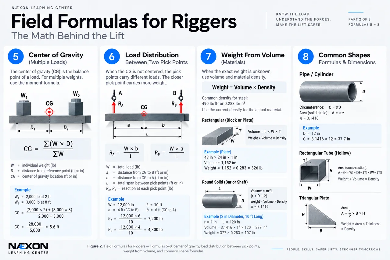
Figure 2. Field Formulas for Riggers — Formulas 5–8: Center of gravity, unequal load distribution between pick points, estimating material weight from volume and density, and common shape calculations used to determine dimensions, volume, and weight in the field.
A load naturally attempts to position its center of gravity beneath the hook.
For multiple known weights along a common reference line:
CG = Σ(W × D) ÷ ΣW
Where:
- W = individual weight
- D = distance from the chosen reference point
- Σ = sum of all values
Example
Suppose a fabricated assembly contains:
- 2,000 lb located 2 ft from the reference
- 3,000 lb located 8 ft from the reference
Calculate the moments:
2,000 × 2 = 4,000 lb-ft
3,000 × 8 = 24,000 lb-ft
Total moment:
28,000 lb-ft
Total weight:
5,000 lb
Therefore:
CG = 28,000 ÷ 5,000
CG = 5.6 ft
The combined center of gravity is 5.6 ft from the reference point.
Knowing where the CG lies is critical because a hook positioned incorrectly relative to the CG can cause the load to rotate or tilt as it comes free.
6. Load Distribution Between Two Pick Points
When the center of gravity is not centered between two pick points, the pick points will not carry equal loads.
For a load supported at points A and B:
Load at A = W × Distance from CG to B ÷ Total Span
Load at B = W × Distance from CG to A ÷ Total Span
Example
A 12,000-lb load is supported by pick points 10 ft apart.
The CG is 4 ft from point A and therefore 6 ft from point B.
At A:
12,000 × 6 ÷ 10 = 7,200 lb
At B:
12,000 × 4 ÷ 10 = 4,800 lb
Check:
7,200 + 4,800 = 12,000 lb
The pick point closer to the CG carries the greater share of the load.
This calculation determines the vertical reaction at each pick point. Sling tension must then be determined from the actual sling geometry.
7. Weight From Volume
When the exact load weight is unavailable, material dimensions and density can sometimes be used to estimate it.
Weight = Volume × Density
For steel, a commonly used approximate density is:
490 lb/ft³
or
0.283 lb/in³
The correct density should be used for the actual material being lifted.
8. Rectangular Steel
For a solid rectangular piece:
Volume = Length × Width × Thickness
Then:
Weight = Volume × Density
Example
A steel plate measures:
48 in × 24 in × 1 in
Volume:
48 × 24 × 1 = 1,152 in³
Using approximately 0.283 lb/in³:
1,152 × 0.283 ≈ 326 lb
The plate weighs approximately 326 lb before accounting for anything attached to it.
9. Solid Round Steel
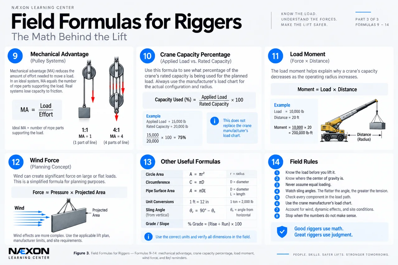
Figure 3. Field Formulas for Riggers — Formulas 9–14: Mechanical advantage, crane capacity percentage, load moment, wind-force considerations, useful field formulas, and essential rigging rules for understanding the forces involved in a lift.
For a solid round:
Volume = πr²L
Then:
Weight = πr²L × Density
Remember that the radius is half the diameter.
For field calculations:
π ≈ 3.1416
This formula can be useful when estimating the weight of shafts, pins, bars, and other cylindrical components.
10. Circumference
Riggers and pipefitters frequently need circumference when laying out or measuring around cylindrical equipment.
C = πD
Where:
- C = circumference
- D = outside diameter
Example
For a 36-in outside diameter:
C = 3.1416 × 36
C ≈ 113.1 in
11. Mechanical Advantage
Ideal mechanical advantage can be expressed as:
MA = Load ÷ Effort
For an ideal pulley system, mechanical advantage can also be approximated by counting the rope parts directly supporting the moving load.
For example, an ideal system with four supporting parts of line has approximately:
4:1 mechanical advantage
An ideal 4,000-lb load would therefore require:
4,000 ÷ 4 = 1,000 lb
of theoretical input force.
Real systems experience friction and other losses, so actual required effort will be greater. Equipment ratings, line pull, sheave efficiency, rigging configuration, and manufacturer requirements remain controlling.
12. Crane Capacity Percentage
A simple comparison can be made with:
Capacity Used (%) = Applied Load ÷ Rated Capacity × 100
For example, if the applicable rated capacity for the crane’s actual configuration and radius is 20,000 lb and the relevant load is 15,000 lb:
15,000 ÷ 20,000 × 100 = 75%
That does not by itself establish that a lift is acceptable. Crane capacity depends on the manufacturer’s load chart and factors such as radius, boom configuration, setup, attachments, and other conditions.
The load handled by the crane can also include more than the object itself. The applicable lift calculation must account for the components required by the load chart and lift plan, which may include rigging, hook/block, lifting beams, shackles, and other below-the-hook equipment.
13. Load Moment
A basic moment calculation is:
Moment = Force × Distance
or, in simple load terms:
Moment = Load × Distance
A 10,000-lb load acting 20 ft from a reference produces:
10,000 × 20 = 200,000 lb-ft
This concept helps explain why crane capacity generally decreases as operating radius increases.
A load that may be manageable close to the crane can become unacceptable farther away.
Always use the crane manufacturer’s applicable load chart rather than attempting to determine crane capacity from this formula alone.
14. Tagline and Wind Considerations
Large vessels, duct sections, tanks, structural assemblies, panels, and similar loads can present substantial surface area to the wind.
A simplified relationship is:
Wind Force ≈ Wind Pressure × Projected Area
But wind effects during lifting are more complicated than this simple expression suggests. Load shape, orientation, gusts, crane configuration, manufacturer restrictions, and site requirements can all matter.
Use the applicable engineered procedure, lift plan, manufacturer limitations, and site wind limits rather than relying on a simple field formula to decide whether a lift should proceed.
The Sling-Angle Trap
Consider the same 10,000-lb load with a symmetrical two-leg bridle.
At 90° from horizontal:
5,000 lb per leg
At 60°:
≈ 5,774 lb per leg
At 45°:
≈ 7,071 lb per leg
At 30°:
10,000 lb per leg
Nothing about the load itself changed.
Only the sling geometry changed.
That is why looking at the weight alone does not tell a rigger everything they need to know about the forces in the rigging.
Common Rigging Math Mistakes
Several calculation errors repeatedly cause problems in the field:
- Assuming two sling legs always divide the load exactly 50/50.
- Confusing an angle measured from horizontal with one measured from vertical.
- Forgetting that decreasing the sling angle from horizontal increases tension.
- Assuming every leg of a multi-leg assembly shares the load equally.
- Ignoring an off-center center of gravity.
- Using nominal dimensions when actual dimensions are required.
- Forgetting the weight of rigging or below-the-hook equipment where it must be included.
- Treating an estimated material weight as though it were a verified load weight.
- Using a crane’s maximum advertised capacity instead of the applicable load-chart capacity for the actual configuration and radius.
- Using formulas as a substitute for equipment ratings, lift planning, or qualified supervision.
Field Rules
Know the load before you lift it.
Verify weight whenever reliable documentation is available.
Know where the center of gravity is.
The hook needs to be appropriately positioned relative to the CG for the intended lift.
Never assume equal loading.
Unequal geometry and an offset CG can produce very different forces between pick points and sling legs.
Watch sling angles.
As a sling becomes flatter toward horizontal, its tension increases rapidly.
Check every component in the load path.
Slings, shackles, hooks, lifting points, spreader beams and other hardware must be suitable for the actual configuration and forces involved.
Use the load chart.
A field formula cannot replace the crane manufacturer’s load chart.
Stop when the numbers do not make sense.
A calculation is a verification tool, not permission to continue with an uncertain lift.
Knowledge Check
1. A 10,000-lb load is lifted symmetrically using two sling legs at 60° from horizontal. Approximately how much tension is in each leg?
Answer: 5,774 lb
2. What happens to sling tension as the sling angle becomes flatter toward horizontal?
Answer: Tension increases.
3. A 12,000-lb load is supported at two points 10 ft apart. The CG is 4 ft from point A. Which point carries more vertical load?
Answer: Point A, because it is closer to the center of gravity.
4. What is the approximate circumference of a 24-in diameter cylinder?
C = π × 24 ≈ 75.4 in
5. Can a load-moment formula replace the manufacturer’s crane load chart?
Answer: No.
Practical Exercise
A fabricated assembly weighs 18,000 lb. Two pick points are 12 ft apart, and the center of gravity is located 5 ft from pick point A.
First calculate the vertical load carried at each pick point.
At A:
18,000 × 7 ÷ 12
= 10,500 lb
At B:
18,000 × 5 ÷ 12
= 7,500 lb
Now imagine that the sling legs from those pick points rise toward a common hook.
The calculation is not finished.
Those values represent the vertical reactions at the pick points. The actual tension in each sling leg depends on that leg’s geometry. This is exactly why a rigger must understand load distribution and sling angle together rather than treating them as separate problems.
Final Takeaway
Rigging math is not about memorizing complicated equations. It is about understanding what happens to a load when geometry changes.
Remember the relationships:
Lower sling angle → greater sling tension.
CG moves toward a pick point → that pick point carries more load.
Crane radius increases → available capacity generally decreases according to the load chart.
More material volume → more weight.
Unknown load or uncertain calculation → verify before lifting.
A good rigger does not simply know how to connect the rigging.
A good rigger understands the forces traveling through it.
I’d pair this with a clean landscape NÆXON field-formula diagram showing sling-angle tension, center of gravity, unequal pick-point loading, and the key equations on one reference sheet.