Industrial pipefitting requires far more math than simply reading measurements from a tape. Every offset, rolling offset, fitting takeoff, elevation change, slope, circumference, and cut length depends on geometry.
A pipefitter who understands the math behind the layout can work backward from dimensions, verify an isometric, identify bad measurements before fabrication, and solve problems when the drawing does not give every dimension needed.
The formulas below are practical field references. Actual fabrication and installation should always be verified against project drawings, specifications, fitting dimensions, applicable codes, and manufacturer data.
1. The 45° Offset
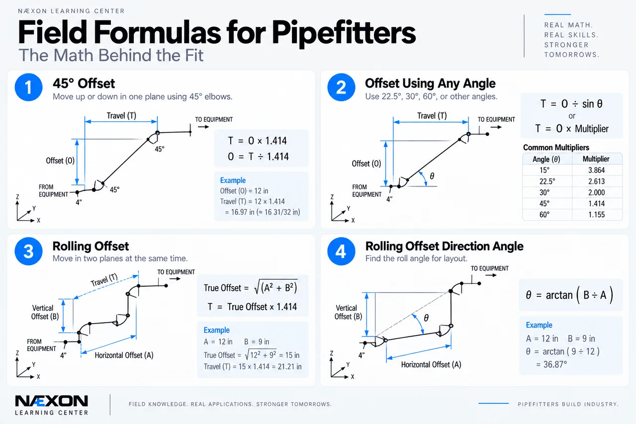
Figure 1. Field Formulas for Pipefitters — Formulas 1–4: Traditional piping-isometric line diagrams showing the geometry behind 45° offsets, offsets using different fitting angles, rolling offsets, and roll-direction calculations. Blue dimensions identify offset, travel, horizontal movement, vertical movement, and layout angles.
One of the most-used pipefitting calculations is the 45° offset.
For a true 45° offset:
Travel = Offset × 1.414
The number 1.414 comes from √2.
Example
Required offset:
12 in
Travel:
12 × 1.414 = 16.968 in
Approximately:
16 31/32 in
In practical field work, the required precision should match the fabrication requirements and measurement method.
Working Backward
If you know the travel:
Offset = Travel ÷ 1.414
This is useful when checking an existing spool.
2. Offset Using Any Angle
Not every offset uses 45° fittings.
For an offset angle θ:
Travel = Offset ÷ sin θ
This can also be written:
Travel = Offset × Travel Multiplier
Common theoretical multipliers are:
Angle
Travel Multiplier
15°
3.864
22.5°
2.613
30°
2.000
45°
1.414
60°
1.155
Example
A 10-in offset using 30° bends:
Travel = 10 × 2
Travel = 20 in
Knowing why the multiplier works is better than simply memorizing a chart.
3. Simple Rolling Offset
A rolling offset moves the pipe in two perpendicular directions at the same time.
Before calculating travel, combine those two offsets into a true offset.
True Offset = √(Horizontal Offset² + Vertical Offset²)
Then, for a 45° rolling offset:
Travel = True Offset × 1.414
Example
Suppose the pipe must move:
12 in horizontally
and
9 in vertically
First calculate the true offset:
True Offset = √(12² + 9²)
= √(144 + 81)
= √225
= 15 in
Now calculate 45° travel:
Travel = 15 × 1.414
≈ 21.21 in
This two-step method is one of the most important pieces of pipefitter geometry.
4. Rolling Offset Direction Angle
Sometimes you also need to determine the direction of the roll.
Roll Angle = arctan(Vertical Offset ÷ Horizontal Offset)
Using the previous example:
Roll Angle = arctan(9 ÷ 12)
≈ 36.87°
That describes the orientation of the combined offset in the plane formed by the two perpendicular movements.
5. Pythagorean Theorem
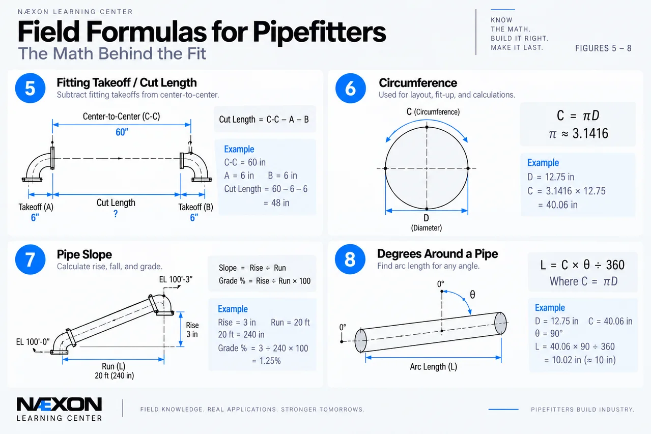
Figure 2. Field Formulas for Pipefitters — Formulas 5–8: Field calculations for fitting takeoff and cut length, pipe circumference, slope and grade, and degrees around a pipe. These formulas help pipefitters translate centerline dimensions, elevations, diameters, and angular positions into accurate fabrication and layout measurements.
The foundation behind many pipefitting calculations is:
a² + b² = c²
Therefore:
c = √(a² + b²)
Pipefitters use this relationship for:
- Rolling offsets
- Diagonal measurements
- Squaring layouts
- Structural crossings
- Equipment connections
- Elevation changes
- Determining true distances
Classic Field Check
A 3-4-5 triangle is square because:
3² + 4² = 5²
9 + 16 = 25
The same relationship works at larger scales:
6-8-10
9-12-15
12-16-20
6. Fitting Takeoff
When determining a pipe cut length between fittings:
Cut Length = Center-to-Center Dimension − Fitting Takeoffs
For two fittings:
Cut Length = C-C − Takeoff₁ − Takeoff₂
Example
Suppose two fitting centerlines are:
60 in apart
Fitting A takeoff:
6 in
Fitting B takeoff:
6 in
Then:
Cut Length = 60 − 6 − 6
Cut Length = 48 in
The critical rule is to use the actual applicable fitting dimensions rather than assuming every fitting has the same takeoff.
7. Fitting Center-to-End
For standard fittings, center-to-end dimensions are normally obtained from the applicable dimensional standard or manufacturer information.
Once the correct dimension is known, it becomes part of the spool calculation.
For a simple elbow-to-elbow spool:
Pipe Cut = Required C-C − CTE₁ − CTE₂
Where:
CTE = Center-to-End
This is why experienced pipefitters identify the exact fittings before calculating cut lengths.
Changing fitting type can change the required pipe length even when the overall spool dimensions stay the same.
8. Circumference
Circumference is used constantly around pipe, vessels, tanks, and layout work.
C = πD
Where:
- C = circumference
- D = actual diameter
- π ≈ 3.1416
Example
For an actual outside diameter of 12.75 in:
C = 12.75 × 3.1416
C ≈ 40.06 in
For pipe work, remember:
Nominal Pipe Size is not necessarily the actual outside diameter.
Use the correct OD for the pipe being measured.
9. Finding Diameter From Circumference
The circumference formula can be reversed:
D = C ÷ π
Example
Measured circumference:
40.06 in
Then:
D = 40.06 ÷ 3.1416
≈ 12.75 in
This can be useful when direct access across the pipe diameter is difficult.
10. Pipe Slope
For gravity piping and other specified slopes:
Slope = Rise ÷ Run
Percentage grade:
Grade % = Rise ÷ Run × 100
Example
A line drops 3 in over 20 ft.
Convert the run to inches:
20 × 12 = 240 in
Then:
3 ÷ 240 × 100
= 1.25%
The line has a:
1.25% slope
11. Rise or Fall From Slope
If the required slope is known:
Rise/Fall = Run × Slope
For percentage grade:
Rise/Fall = Run × (Grade % ÷ 100)
Example
A line runs:
30 ft
Required slope:
2%
Convert:
30 ft × 0.02 = 0.6 ft
Then:
0.6 × 12 = 7.2 in
Required elevation change:
7.2 in
The direction determines whether that is a rise or fall.
12. Degrees Around a Pipe
A complete circle contains:
360°
Therefore:
Arc Length = Circumference × Angle ÷ 360
Example
Pipe circumference:
48 in
Required rotation:
90°
Arc Length = 48 × 90 ÷ 360
= 12 in
A quarter turn around that circumference equals 12 in.
For 45°:
48 × 45 ÷ 360 = 6 in
This relationship is useful when laying out positions around pipe.
13. Pipe Cross-Sectional Area
For the inside flow area of a circular pipe:
A = π × ID² ÷ 4
or:
A = πr²
Where:
- A = internal cross-sectional area
- ID = actual inside diameter
- r = inside radius
Example
If the actual ID is 8 in:
A = 3.1416 × 8² ÷ 4
A ≈ 50.27 in²
Schedule matters because different wall thicknesses can produce different IDs for the same nominal pipe size.
14. Pipe Internal Volume
For a straight cylindrical internal volume:
Volume = Area × Length
Therefore:
V = π × ID² ÷ 4 × L
Keep the units consistent.
If ID and length are measured in inches, the result will be cubic inches.
Useful Conversion
1 U.S. gallon = 231 in³
Therefore:
Gallons = Cubic Inches ÷ 231
This can help estimate the approximate internal capacity of straight pipe, although an actual system may also contain fittings, valves, equipment, elevation differences, trapped volumes, and other components.
15. Elevation Difference
When working from two known elevations:
Elevation Difference = Final Elevation − Starting Elevation
Example
Starting centerline elevation:
EL 102’-6”
Final centerline elevation:
EL 105’-0”
Difference:
2’-6”
or:
30 in
That 30-in elevation difference can then become one leg of an offset or rolling-offset calculation.
16. Converting Decimal Inches to Fractions
Field measurements often need to move between decimal and fractional inches.
To convert a decimal to the nearest sixteenth:
Decimal × 16
Example:
0.625 × 16 = 10
Therefore:
0.625 in = 10/16 = 5/8 in
For thirty-seconds:
Decimal × 32
Example:
0.40625 × 32 = 13
Therefore:
0.40625 in = 13/32 in
The required rounding should always match the tolerance of the work.
The Rolling-Offset Trap
A common mistake is multiplying one of the individual offsets by 1.414 before finding the true offset.
Suppose you need:
12 in horizontal
and:
16 in vertical
Do not simply calculate:
16 × 1.414
First find the true offset:
√(12² + 16²)
= √400
= 20 in
Then calculate the 45° travel:
20 × 1.414
≈ 28.28 in
The individual 12-in and 16-in dimensions describe two different directions.
The 20-in true offset is the diagonal displacement the fitting arrangement actually has to overcome.
Common Pipefitting Math Mistakes
Several mistakes can turn a correct drawing into a bad spool:
- Using nominal pipe size instead of actual OD.
- Forgetting fitting takeoffs when calculating cut length.
- Using the wrong fitting’s center-to-end dimension.
- Treating a rolling offset like a simple offset.
- Applying 1.414 before determining the true offset.
- Mixing feet and inches in the same equation.
- Reading elevation incorrectly.
- Confusing centerline dimensions with face-to-face dimensions.
- Using the wrong fitting angle.
- Rounding too early in a calculation.
- Assuming all fittings from different types or manufacturers have identical dimensions.
- Fabricating before verifying field dimensions.
Field Rules
Find the geometry before reaching for the calculator.
Determine whether you’re dealing with a simple offset, rolling offset, slope, rotation, or combination.
Work from centerlines.
Many piping dimensions are established around pipe and fitting centerlines.
Know the actual fitting.
Long-radius elbows, short-radius elbows, reducers, tees, flanges, valves, and specialty fittings all affect spool dimensions differently.
Keep units consistent.
Convert everything to inches or everything to feet before performing calculations when necessary.
Do not round too early.
Carry sufficient precision through the calculation, then round the final result to the tolerance required by the job.
Verify OD.
Nominal pipe size and outside diameter are different concepts.
Check elevations twice.
A wrong elevation can turn a correct offset into a spool that cannot be installed.
Measure the field when required.
A perfect calculation based on a bad field dimension still produces a bad spool.
Knowledge Check
1. What is the travel of a 10-in 45° offset?
10 × 1.414 = 14.14 in
2. A rolling offset moves 6 in horizontally and 8 in vertically. What is the true offset?
√(6² + 8²) = 10 in
3. What is the formula for circumference?
C = πD
4. A pipe drops 2 in over a 100-in horizontal run. What is the grade?
2 ÷ 100 × 100 = 2%
5. Why should nominal pipe size not automatically be used in a circumference calculation?
Because NPS does not necessarily equal the pipe’s actual outside diameter.
Practical Exercise
A pipe must move:
9 in horizontally
and:
12 in vertically
using a 45° rolling offset.
First determine the true offset:
True Offset = √(9² + 12²)
= √(81 + 144)
= √225
= 15 in
Now determine theoretical travel:
Travel = 15 × 1.414
≈ 21.21 in
Now suppose the spool calculation requires subtracting two applicable fitting takeoffs of 6 in each from that center-to-center travel.
Cut Length = 21.21 − 6 − 6
≈ 9.21 in
But this last calculation is only valid if 6 in is actually the correct takeoff for each specific fitting and the stated dimensions represent the correct center-to-center geometry.
That verification is what separates simply knowing the formula from knowing how to apply it.
Final Takeaway
Pipefitting math becomes easier when you stop treating the formulas as unrelated tricks and start seeing the geometry behind them.
Remember:
45° offset → Offset × 1.414
Rolling offset → Find true offset first.
Cut length → Overall centerline dimension minus applicable fitting takeoffs.
Circumference → π × actual diameter.
Slope → Rise ÷ Run.
Arc length → Circumference × Angle ÷ 360.
Bad input dimensions → bad spool, no matter how accurate the math is.
A good pipefitter can memorize a multiplier.
A great pipefitter understands why it works.