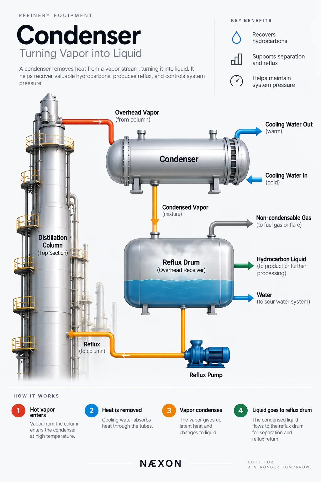
A condenser is one of the most important heat-transfer devices in a refinery. Its job sounds simple: remove enough heat from a vapor stream to turn some or all of that vapor into liquid. But that phase change plays a critical role in distillation, product recovery, pressure control, steam systems, vacuum systems, and many other refinery processes.
For pipefitters, welders, operators, mechanics, and maintenance crews, understanding a condenser means understanding more than the exchanger itself. You need to know where the vapor enters, where the condensate leaves, what happens to non-condensable gases, how cooling water flows, why pressure matters, and what symptoms appear when the condenser begins losing performance.
What Is a Condenser?
A condenser is a heat exchanger specifically used to condense vapor into liquid.
Hot vapor enters the condenser and transfers heat through a metal surface to a colder cooling medium. As the vapor loses its latent heat, it reaches its condensation temperature and changes phase.
A simplified process looks like:
Hot Vapor → Condenser → Condensed Liquid
At the same time:
Cooling Medium In → Absorbs Heat → Cooling Medium Out
The two fluids normally remain physically separated by the exchanger tubes or plates.
In refinery service, the cooling medium may be cooling water, air, refrigerant, or another process stream. Cooling water and air cooling are especially common.
Why Refineries Need Condensers
Refinery processes frequently heat hydrocarbons until portions of the process stream become vapor. Those vapors cannot always remain gaseous.
Condensers allow the refinery to recover valuable hydrocarbons and return them to liquid form.
They are commonly used to:
- Condense overhead vapor from distillation columns.
- Recover liquid hydrocarbon products.
- Produce reflux for fractionation towers.
- Maintain desired tower operating pressure.
- Condense steam.
- Reduce vapor volume before downstream separation.
- Support vacuum-producing systems.
- Recover condensable material before gases continue downstream.
Without adequate condensation, the entire operating balance of a fractionation system can change.
The Basic Heat-Transfer Principle
The condenser works because heat naturally moves from the hotter fluid toward the colder fluid.
Consider a shell-and-tube condenser.
Hot hydrocarbon vapor may enter the shell side while cooling water travels through the tubes. The two fluids never intentionally mix.
Heat travels:
Hot Vapor → Tube Wall → Cooling Water
The vapor gives up heat.
The cooling water gains heat.
Eventually, enough energy is removed from the vapor that it undergoes a phase change:
Vapor → Liquid
This phase change is especially important because a large amount of energy can be transferred as latent heat while the fluid is condensing.
Sensible Heat vs. Latent Heat
Understanding this distinction makes condenser operation much easier to understand.
Sensible heat changes the temperature of a substance without changing its phase.
For example:
300°F vapor → 250°F vapor
The temperature changed, but the material remained vapor.
Latent heat is associated with changing phase.
For example:
Vapor → Liquid
During condensation, significant heat can be removed while the fluid undergoes the vapor-to-liquid transition.
This is why condensers can transfer enormous amounts of thermal energy.
Major Components of a Shell-and-Tube Condenser
Although condenser designs vary, a refinery shell-and-tube condenser commonly contains several major components.
Shell
The shell is the large cylindrical pressure-containing body surrounding the tube bundle.
One process fluid travels through the shell side.
Tube Bundle
Hundreds or sometimes thousands of tubes may run through the exchanger.
The second fluid travels through these tubes while heat transfers through the tube walls.
Tubesheets
The tubesheets secure and separate the exchanger tubes.
Tube ends are typically expanded, welded, or otherwise mechanically secured to the tubesheet depending on the design.
Channel Head or Bonnet
The channel head distributes the tube-side fluid into the tubes.
For cooling-water service, removing the channel head can provide maintenance access to the tube ends.
Baffles
Baffles direct shell-side flow across the tube bundle and support the tubes.
Their arrangement improves heat transfer while controlling flow behavior.
Nozzles
The condenser requires connections for the process and cooling streams.
Depending on the design, these can include:
- Vapor inlet.
- Condensate outlet.
- Cooling-water inlet.
- Cooling-water outlet.
- Vent connection.
- Drain connection.
- Pressure and temperature instrumentation.
The nozzle arrangement matters greatly because vapor, liquid, and non-condensable gases behave differently inside the equipment.
Where You Find Condensers in a Refinery
One of the most recognizable applications is at the top of a distillation or fractionation tower.
Imagine the system:
Distillation Column → Overhead Vapor Line → Condenser → Reflux Drum
Vapor leaves the top of the tower and enters the condenser.
The condenser removes heat and converts much of that vapor into liquid.
The resulting mixture then enters an overhead receiver or reflux drum.
Inside that drum, phases can separate. Depending on the process, you may have hydrocarbon liquid, water, and non-condensable gas.
Part of the hydrocarbon liquid may then be pumped back toward the tower as reflux.
The remainder can continue toward downstream processing or product handling.
What Is Reflux?
Reflux is condensed overhead liquid that is returned to the upper portion of a distillation column.
This liquid flows downward through the tower while vapor rises upward.
That countercurrent contact helps improve separation.
The basic loop is:
Tower Overhead → Condenser → Reflux Drum → Reflux Pump → Tower
Because of this relationship, condenser performance can directly influence tower separation.
A condenser problem may therefore appear somewhere else in the process before crews realize the condenser is responsible.
Total Condenser vs. Partial Condenser
Not every condenser is designed to turn the entire vapor stream into liquid.
Total Condenser
A total condenser is designed to condense essentially the entire condensable vapor stream.
The outlet is predominantly liquid, aside from non-condensable gases or operating exceptions.
Partial Condenser
A partial condenser intentionally condenses only part of the incoming vapor.
The outlet contains both vapor and liquid.
This can provide another separation step because components with different volatility behave differently during partial condensation.
Cooling-Water Condensers
Cooling water is widely used as the heat sink for refinery condensers.
A simplified circuit is:
Cooling Tower → Cooling-Water Pump → Condenser → Warm Cooling Water → Cooling Tower
The cooling tower rejects the absorbed heat to the atmosphere, and the cooled water is circulated back through the refinery.
This demonstrates how multiple pieces of refinery equipment work together.
A condenser cannot perform properly if the cooling-water system supplying it is inadequate.
Air-Cooled Condensation
Some services use air instead of circulating cooling water.
Process fluid travels through finned tubes while large fans move ambient air across the tube surfaces.
This eliminates or reduces cooling-water demand, but performance becomes more dependent on atmospheric conditions.
A hot summer afternoon can create very different cooling conditions than a cold winter night.
Why Condenser Pressure Matters
Condensation and pressure are closely related.
Changing system pressure changes the temperature at which a fluid condenses.
In a distillation system, poor condenser performance can cause overhead pressure to increase because vapor is not being condensed quickly enough.
That can affect:
- Tower temperatures.
- Vapor-liquid equilibrium.
- Product separation.
- Reflux conditions.
- Equipment loading.
- Relief-system demand.
Operators therefore pay close attention to condenser performance when troubleshooting abnormal tower pressure.
Non-Condensable Gases
Not everything entering a condenser necessarily becomes liquid.
Hydrogen, nitrogen, light hydrocarbons, air leakage, and other gases may remain gaseous under the operating conditions.
These are commonly called non-condensables.
They must have somewhere to go.
If non-condensable gases accumulate in portions of the condenser, they can reduce the effective heat-transfer area and interfere with condensation.
This is why venting and vapor-outlet arrangements are important.
Common Condenser Problems
Tube Fouling
Deposits can build up inside or outside exchanger tubes.
Cooling-water systems may produce mineral scale, biological growth, corrosion products, or debris.
Process-side fouling can also occur.
As deposits become thicker, they create additional resistance to heat transfer.
Tube Plugging
Individual tubes may become partially or completely restricted.
Reduced flow through the tube bundle decreases exchanger performance and can create uneven flow distribution.
Tube Leaks
A failed tube can allow the two fluids to communicate.
In hydrocarbon/cooling-water service, this can potentially introduce hydrocarbons into the cooling-water system or cooling water into the process.
Tube leakage therefore requires careful investigation.
Corrosion
Condenser components can experience several corrosion mechanisms depending on metallurgy, water chemistry, process composition, velocity, temperature, and contaminants.
Poor Cooling-Water Flow
Even a perfectly clean condenser cannot perform correctly without sufficient cooling-medium flow.
Potential causes include restricted piping, pump problems, fouled strainers, valve position problems, cooling-tower limitations, or exchanger fouling.
Air Binding and Non-Condensable Accumulation
Gas trapped in inappropriate locations can reduce the effective heat-transfer surface.
Proper vent arrangements are therefore essential.
Signs of Poor Condenser Performance
Operators and maintenance personnel may notice several warning signs:
- Higher-than-normal overhead pressure.
- Higher condenser outlet temperature.
- Reduced condensate production.
- Abnormal reflux conditions.
- Increasing cooling-water outlet temperature.
- Poor product separation.
- Abnormal exchanger differential pressure.
- Process instability.
- Unexpected vent-gas loading.
One symptom alone does not prove the condenser is responsible. Troubleshooting requires looking at the entire system.
Inspection and Maintenance
During shutdowns and turnarounds, condensers may be opened for detailed inspection.
Maintenance activities can include removing channel heads, inspecting tubesheets, cleaning tubes, checking for erosion or corrosion, inspecting gasket surfaces, performing nondestructive examination, hydrotesting, and plugging damaged tubes when permitted by engineering requirements.
Tube bundles may sometimes be pulled from the shell for more extensive inspection and repair.
For tradespeople, these jobs can involve substantial rigging, bolting, piping removal, exchanger-head handling, gasket replacement, and precise reassembly.
Field Knowledge for Pipefitters
Condensers often have large process and utility piping attached to them. That piping should never be treated as though nozzle location and alignment are flexible.
Pipefitters should pay close attention to:
- Nozzle orientation.
- Pipe support locations.
- Thermal expansion.
- Flange alignment.
- Equipment nozzle loading.
- Vent and drain orientation.
- Cooling-water supply and return identification.
- Process flow direction.
- Gasket specification.
- Bolt-up requirements.
Forcing piping into alignment with exchanger nozzles can transfer unwanted loads directly into the equipment.
Safety Around Condensers
A condenser may contain high-pressure hydrocarbons, toxic process materials, hot liquids, steam, cooling water, or residual trapped pressure depending on service.
Before maintenance, workers must rely on the facility’s approved isolation and energy-control procedures.
Important hazards can include:
- Trapped pressure.
- Residual hydrocarbons.
- Hydrogen sulfide exposure in applicable refinery services.
- Hot surfaces and fluids.
- Heavy exchanger heads.
- Suspended loads during maintenance.
- Confined-space hazards when applicable.
- Unexpected liquid trapped behind blinds or low points.
- Pyrophoric deposits in certain hydrocarbon services.
Never assume an exchanger is safe simply because upstream equipment has been shut down.
Troubleshooting Example
Suppose a fractionation tower begins experiencing increasing overhead pressure.
The condenser should be part of the investigation.
Crews and operators might evaluate whether cooling-water flow has decreased, cooling-water inlet temperature has increased, tubes have fouled, non-condensables are accumulating, process vapor loading has increased, valves are incorrectly positioned, or instrumentation is providing misleading information.
This is an important refinery troubleshooting principle:
The equipment showing the symptom is not necessarily the equipment causing the problem.
A tower pressure problem can originate in the condenser connected to it.
Important Condenser Terminology
- Condensation: Vapor changing into liquid.
- Condensate: Liquid produced through condensation.
- Latent heat: Energy associated with a phase change.
- Shell side: Fluid flowing through the exchanger shell around the tubes.
- Tube side: Fluid flowing through the tubes.
- Tubesheet: Plate that supports and seals the exchanger tubes.
- Non-condensables: Gases that remain vapor under condenser operating conditions.
- Reflux: Condensed overhead liquid returned to a fractionation column.
- Fouling: Deposits that reduce heat-transfer performance.
- Approach temperature: A temperature relationship used to evaluate exchanger cooling performance.
Field Rules
- Trace the entire system. Understand what equipment feeds the condenser and where its outlet goes.
- Never assume the large nozzle is automatically the inlet. Verify drawings and flow direction.
- Know which fluid is on the shell side and which is on the tube side.
- Look for vents at high points and drains at low points.
- Poor condenser performance can create problems elsewhere in the process.
- Protect equipment nozzles from excessive piping loads during installation and maintenance.
- Treat exchanger heads and bundles as serious rigging operations.
- Verify isolation and zero-energy conditions before opening any exchanger.
Knowledge Check
- What is the primary purpose of a condenser?
- What happens to the latent heat when vapor condenses?
- Why can poor condenser performance increase distillation-column pressure?
- What is the difference between a total and partial condenser?
- What is reflux?
- Why are non-condensable gases important?
- What can tube fouling do to condenser performance?
- What could a leaking exchanger tube allow to happen?
- Why should piping never be forced into alignment with a condenser nozzle?
- What equipment commonly follows an overhead condenser in a fractionation system?
Practical Exercise
Using a refinery process flow diagram or simplified training drawing, locate a distillation-column overhead condenser.
Trace the system from:
Tower → Overhead Vapor Line → Condenser → Reflux Drum → Reflux Pump → Tower
Then identify the cooling-medium supply and return.
Finally, determine which lines could contain vapor, condensed hydrocarbon, water, non-condensable gas, and reflux.
Being able to trace that complete circuit is far more valuable in the field than simply recognizing what a condenser looks like.
The Big Picture
A refinery condenser isn’t simply an exchanger that makes something colder. It is often a critical part of the separation process.
By removing heat and changing vapor back into liquid, the condenser allows hydrocarbons to be recovered, reflux to be produced, tower pressure to be controlled, and downstream separation to continue.
For anyone working around refinery equipment, remember the basic relationship:
Vapor enters. Heat leaves. Liquid forms.
Once you understand that relationship—and how the condenser connects to the tower, reflux drum, cooling system, and process piping—the entire overhead system becomes much easier to understand.