A good pipe saddle starts before the grinder ever touches the pipe.
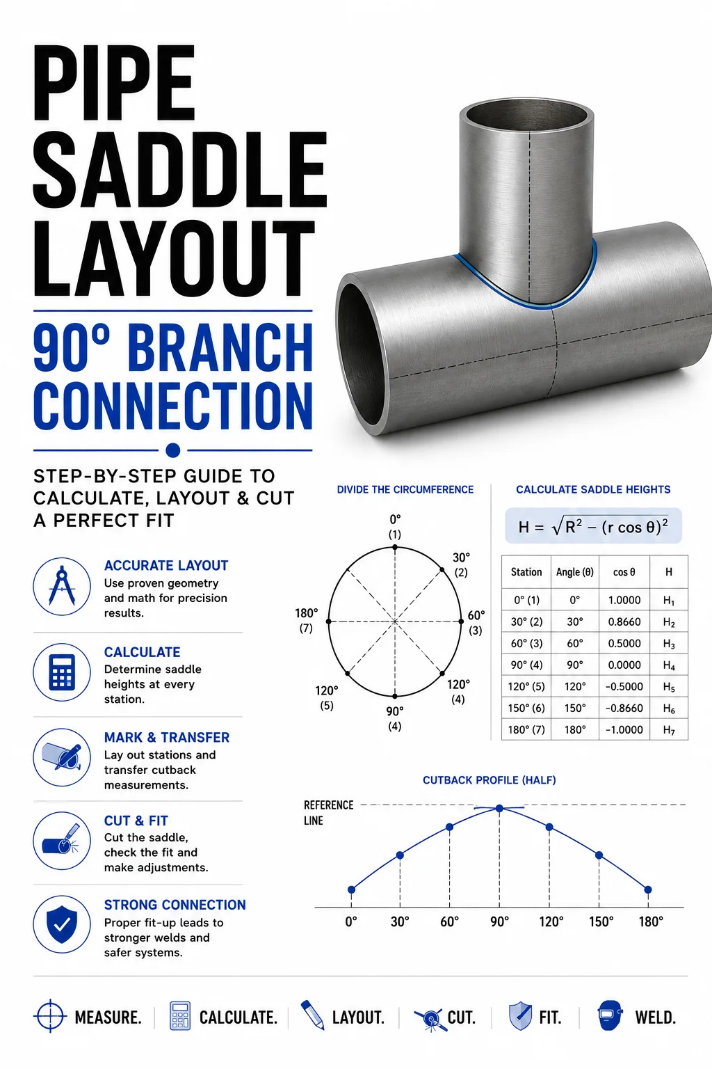
You need the correct pipe outside diameters, the correct branch angle, the correct location of the branch, and a pattern that accurately represents the intersection between the two pipes. Traditionally, getting there can mean circumference calculations, degree divisions, ordinate measurements, graph paper, or manually laying out the cut directly on the pipe.
Rapit Pro gives pipefitters and fabricators another way to do it.
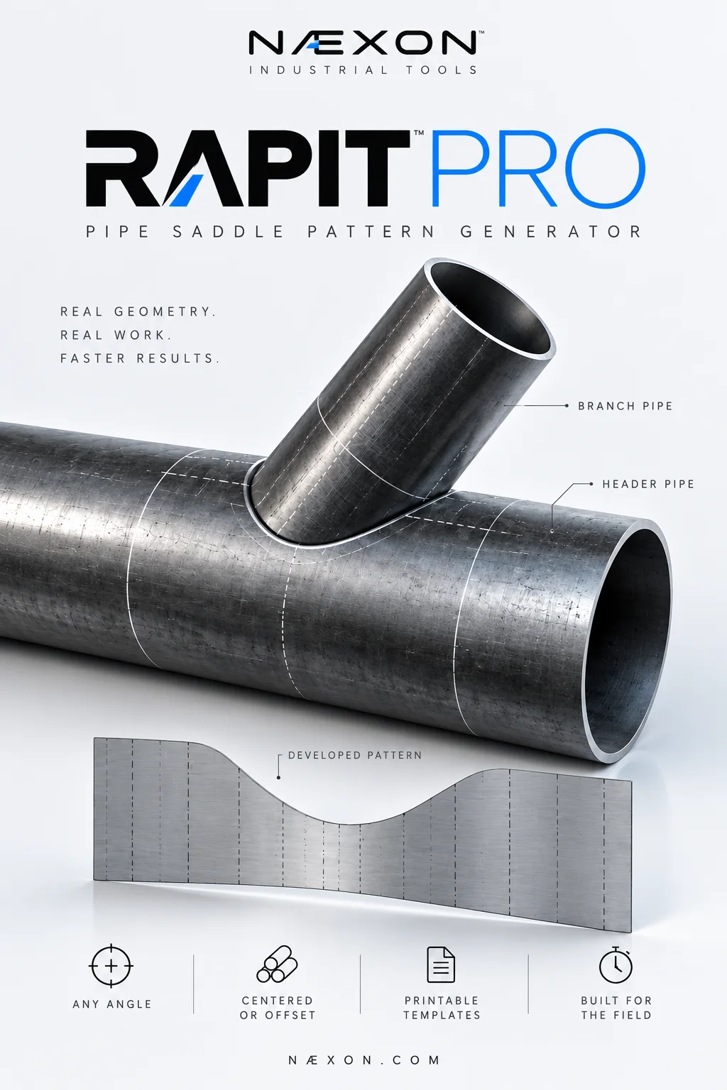
The Næxon pipe saddle and lateral pattern generator calculates the theoretical intersection between two round pipes and develops that geometry into a pattern you can inspect, print, and transfer to the branch pipe.
This guide walks through the process from beginning to end.
Before You Start: Know the Branch and the Header
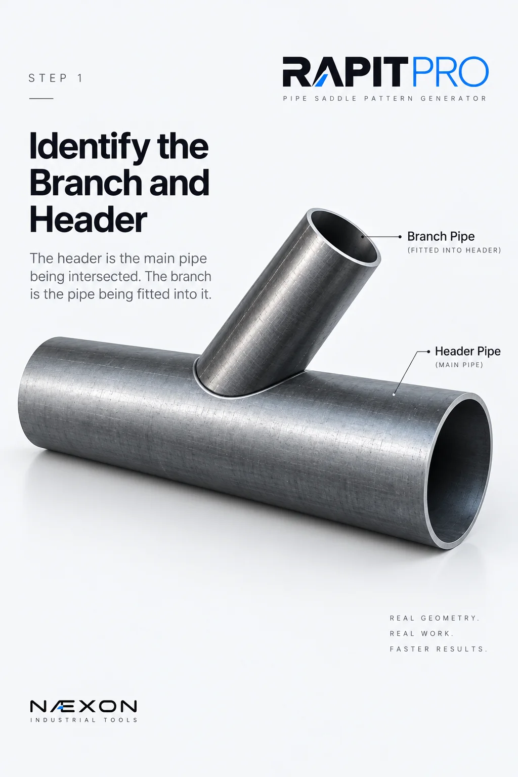
Step 1 — Identify the branch and header. The branch is the pipe being fitted and cut, while the header is the main pipe it intersects.
Before entering anything into Rapit Pro, identify which pipe is the branch and which is the header.
The header is the pipe being intersected.
The branch is the pipe being fitted into it.
This distinction matters because Rapit Pro uses the geometry of both pipes to determine the shape required at the end of the branch.
You should know at minimum:
- Branch pipe size or actual outside diameter
- Header pipe size or actual outside diameter
- Angle between the two pipe centerlines
- Whether the connection is centered or offset
If you want to understand the manual geometry behind this process first, read Saddle Pipe Layout: Circumference and Degrees in the Næxon Learning Center.
Understanding the layout makes the digital tool much more useful because you can recognize whether the generated result makes sense.
Step 1: Choose Inches/NPS or Millimeters/DN
Open Rapit Pro and start under Units & Pipe Sizes.
Rapit Pro gives you two measurement systems:
Inches / NPS
or
Millimeters / DN
Choose the system that matches the pipe information you’re working with.
For most U.S. industrial piping applications, this will normally be Inches / NPS.
Changing units affects how your dimensions and pattern information are displayed, so establish this before entering the rest of the connection.
Step 2: Select the Branch Pipe Size
Next, select the size of the branch pipe.
Remember:
The branch is the pipe that will receive the saddle or fish-mouth cut.
When a standard pipe size is selected, Rapit Pro provides the corresponding outside-diameter information.
Always pay attention to the Branch OD field.
Nominal pipe size is not necessarily the pipe’s actual outside diameter.
For example, a nominal 6-inch pipe has an outside diameter of 6.625 inches.
That actual OD is what matters when developing the geometry.
Step 3: Select the Header Pipe Size
Now enter the header size.
The header is the pipe that the branch will intersect.
Again, check the Header OD rather than relying only on the nominal designation.
The relationship between branch OD and header OD has a major effect on the resulting saddle.
A small branch entering a large header produces a different developed curve than a branch that is much closer to the header diameter.
Rapit Pro calculates the pattern from that actual geometric relationship.
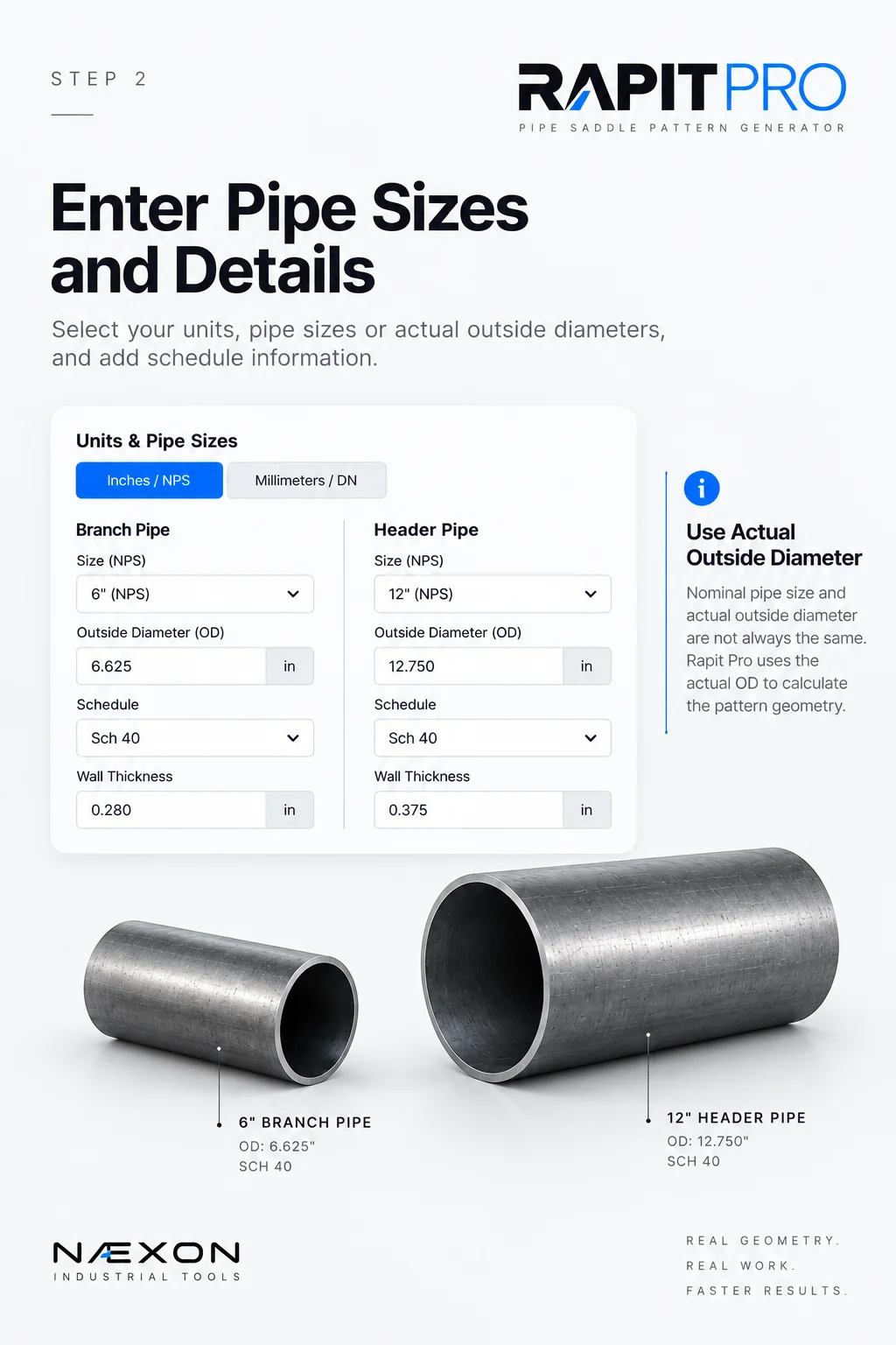
Step 2 — Enter the branch and header pipe sizes and verify their actual outside diameters (OD). Rapit Pro uses the actual OD to calculate accurate saddle pattern geometry.
Step 4: Verify the Outside Diameters
Before moving farther down the page, stop and verify:
Branch OD
and
Header OD
These are two of the most important inputs in the entire calculation.
If either OD is incorrect, the generated saddle geometry will also be incorrect.
Don’t assume.
Verify the material you’re actually fabricating.
This is particularly important when working with tubing, unusual material, nonstandard dimensions, or anything where the actual outside diameter may not match what you’re expecting.
Field Rule: Wrong OD = wrong pattern.
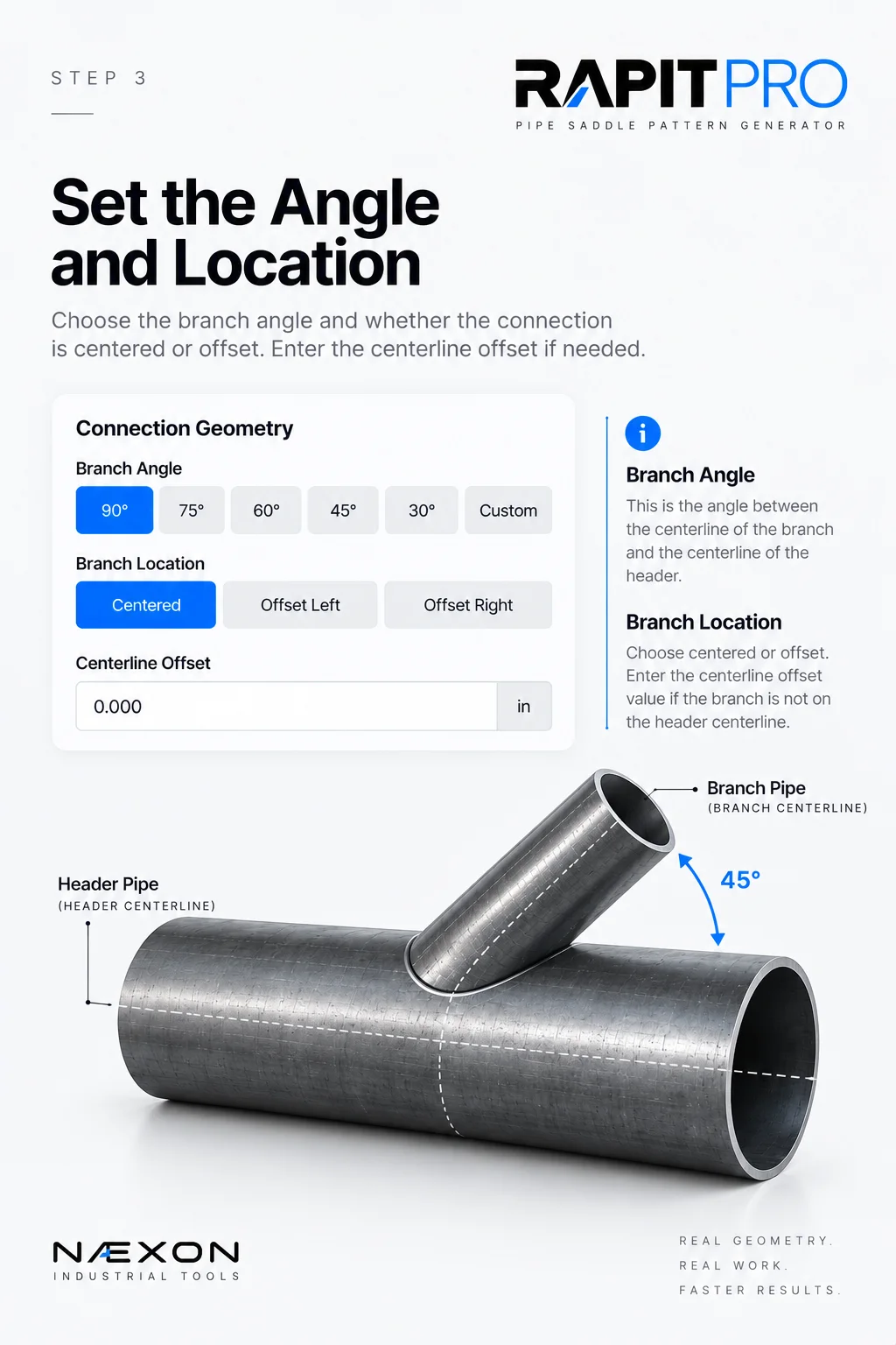
Step 3 — Set the branch angle and connection location. Choose centered or offset geometry, then enter the centerline offset when needed so Rapit Pro can accurately develop the saddle pattern.
Step 5: Add Schedule and Wall-Thickness Information
Rapit Pro also allows you to select or enter information for:
Branch schedule
Header schedule
Branch wall thickness
Header wall thickness
These fields provide useful fabrication reference information.
However, it’s important to understand the distinction between this information and the actual saddle geometry.
The outside-surface intersection is controlled primarily by the outside diameters, branch angle, and centerline offset.
Schedule and wall thickness are provided as fabrication references.
Step 6: Set the Branch Angle
Now move into Connection Geometry.
This is where Rapit Pro becomes considerably more useful than a calculator limited to a standard 90-degree saddle.
The Branch Angle represents the angle between the centerline of the branch and the centerline of the header.
Rapit Pro provides quick selections for:
90°
75°
60°
45°
30°
You can also enter another angle when the connection requires something different.
A conventional perpendicular branch-to-header connection uses 90°.
An angled lateral requires a different angle.
Changing that angle changes the entire developed pattern.
That’s why a 90-degree saddle pattern should not simply be reused for a 45-degree lateral.
The geometry is different.
Step 7: Choose Centered or Offset
Next, determine where the branch centerline sits relative to the header.
Rapit Pro provides three options:
Centered
Offset Left
Offset Right
For a centered connection, the centerline offset is zero.
If the branch is eccentric to the header, select the appropriate direction and enter the required centerline offset.
This is an important capability because not every real-world branch connection lands directly on the header centerline.
An offset changes the intersection geometry and therefore changes the developed cut.
Example: Build a Basic 90° Saddle
Let’s run through a simple example.
Suppose you’re fitting:
Branch: 6-inch NPS
Branch OD: 6.625”
Header: 12-inch NPS
Header OD: 12.750”
Branch angle: 90°
Branch location: Centered
Centerline offset: 0”
This is a straightforward centered 90-degree branch-to-header connection.
After entering those values, Rapit Pro can calculate the theoretical intersection and develop the branch pattern.
This same example is useful because you can compare the digital result with the manual saddle principles explained in Næxon’s Saddle Pipe Layout: Circumference and Degrees.
Step 8: Understand the Fabrication Adjustments
Rapit Pro includes additional fields under Fabrication Adjustments:
Axial cut allowance
Kerf reference
Root gap reference
Bevel angle
These should not all be treated as automatic modifications to the cut line.
The axial cut allowance can shift the generated trace line.
Kerf, root gap, and bevel information are provided as fabrication references because the proper compensation can depend on the cutting method, welding procedure, material, joint design, and project requirements.
This distinction is important.
Rapit Pro helps develop the geometry.
It doesn’t replace the applicable fabrication procedure or WPS.
Step 9: Add the Pattern Information
Before generating the final pattern, Rapit Pro allows you to attach identifying information to it.
Available fields include:
Project
Line / Spool No.
Drawing / Joint
Prepared By
Notes
These fields are optional, but they’re especially useful in a fabrication shop where several patterns may be generated for different spools or joints.
A printed pattern labeled only with a pipe size can become confusing quickly.
A pattern labeled with the project, spool, drawing, and joint can be identified much more easily.
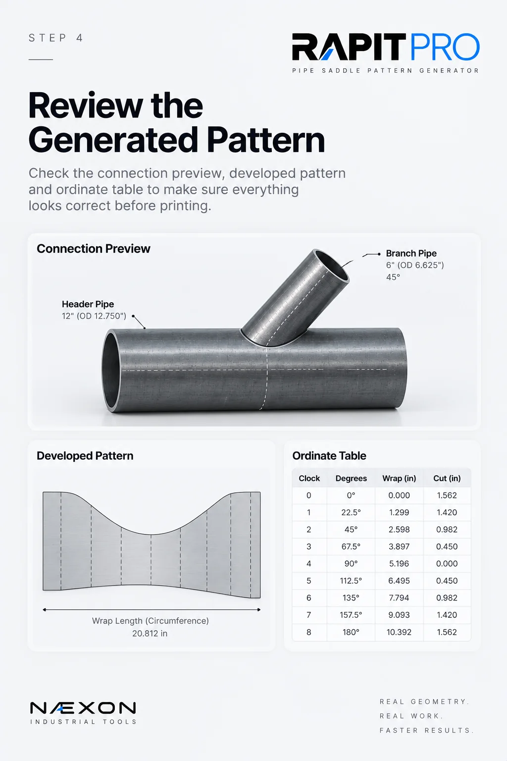
Review the generated pattern. Check the connection preview, developed saddle pattern, and ordinate table to verify the geometry before downloading or printing.
Step 10: Generate the Pattern
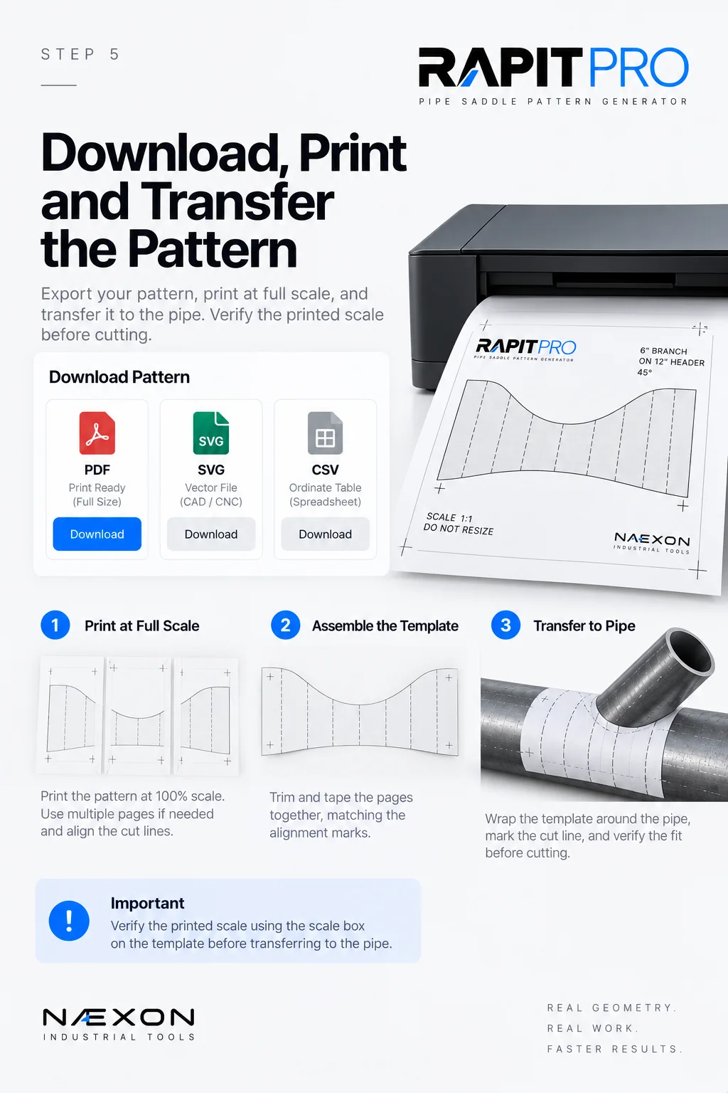
Download, print, and transfer the pattern. Print the Rapit Pro template at full scale, verify the scale, assemble tiled pages if needed, then wrap the pattern around the pipe and mark the cut line.
Once the geometry has been entered and checked, select:
Generate Printable Pattern
Rapit Pro processes the inputs and develops the theoretical intersection between the two round pipes.
Don’t immediately print and start cutting.
First, inspect what the program generated.
Step 11: Check the Connection Preview
Rapit Pro includes a Connection Preview.
Use it.
This gives you a visual representation of the relationship between the branch and header.
Look at the connection and ask:
Does the branch angle look correct?
Is the branch positioned on the correct side?
Does an offset connection visually match what I’m trying to fabricate?
Does the overall geometry make sense?
A preview won’t replace dimensional verification, but it can help catch an obvious input mistake before it reaches the pipe.
Step 12: Examine the Developed Pattern
Next, inspect the Developed Pattern Overview.
This is essentially what happens when the circumference of the branch is opened and laid flat.
Instead of looking at a curved cut wrapped around a cylinder, you’re seeing the cut profile developed across the branch circumference.
This is the shape that eventually becomes your fabrication template.
If you understand traditional saddle layout, this should look familiar.
Manual layout establishes points around the circumference and determines the required cut depth at those locations.
Rapit Pro performs that geometric development digitally.
Step 13: Read the Ordinate Table
Rapit Pro also provides an ordinate table containing:
Clock
Degrees
Wrap Distance
Cut Ordinate
This is extremely useful for understanding and checking the pattern.
Clock identifies the position around the pipe.
Degrees describes that circumferential position mathematically.
Wrap Distance tells you how far around the branch circumference that position occurs.
Cut Ordinate provides the corresponding location of the developed cut.
This connects the digital pattern directly back to traditional pipe-layout principles.
A fitter who understands ordinates can use this information as another way to evaluate the generated pattern rather than relying solely on the graphic.
Step 14: Choose the Paper and Orientation
When you’re ready to produce a physical template, select your:
Paper / plotter size
and
Orientation
A full-size pipe pattern may be much larger than an ordinary sheet of printer paper.
Rapit Pro can generate a true-scale tiled PDF, allowing a larger pattern to be distributed across multiple sheets.
Those sheets can then be assembled to create the complete pattern.
Step 15: Download the Pattern
Rapit Pro currently provides several output options:
Download PDF
Download SVG
Download Ordinate CSV
Each serves a different purpose.
The PDF is particularly useful for producing a printable fabrication template.
SVG provides scalable vector geometry.
The CSV provides the ordinate information as data.
Choose the format appropriate for what you’re doing.
Step 16: Verify Printer Scale Before Using the Pattern
This step matters.
A mathematically correct pattern printed at the wrong scale is still a wrong pattern.
Printer software can automatically shrink or enlarge documents to fit a page.
Before transferring a printed template to pipe, verify that it printed at the intended scale.
Avoid blindly using settings such as Fit to Page when they alter the pattern dimensions.
Check the printed pattern against known dimensions before using it for fabrication.
Field Rule: Generate it. Print it. Measure it. Then trust it.
Step 17: Assemble the Tiled Pattern
If Rapit Pro divided the pattern across multiple sheets, arrange those sheets in their proper positions.
Carefully align the corresponding edges and reference information.
Secure the pages so they cannot move relative to one another.
The finished assembly should reproduce the complete developed circumference of the branch.
Before transferring anything to the pipe, perform another dimensional check.
Step 18: Transfer the Pattern to the Branch Pipe
Once the template has been verified, it can be positioned around the branch pipe according to the fabrication method being used.
Keep the pattern square and correctly oriented.
Make sure the ends align properly around the circumference.
Then transfer the cut profile to the pipe.
At this point, the digital calculation has become a physical layout.
The same principle applies whether the pattern came from Rapit Pro, graph paper, an ordinate table, or a traditional hand layout:
The layout must be verified before material is cut.
Sharing a Rapit Pro Pattern
Rapit Pro also includes a Copy Link function.
When used through Næxon, the link can reload the same pattern inputs for another user.
That can be useful when multiple people need to review the same connection.
For example, a fitter could establish the geometry and send the configuration to another fitter or foreman for review.
The person receiving it can see the same input setup instead of manually recreating every value.
It’s still important for the person performing the fabrication to independently verify the measurements against the actual material and drawings.
Common Mistakes to Avoid
Using Nominal Size as Actual OD
A 6-inch nominal pipe isn’t 6.000 inches OD.
Always verify the actual outside diameter.
Reversing the Branch and Header
The branch receives the saddle cut.
The header is the pipe it intersects.
Keep them straight.
Entering the Wrong Branch Angle
The angle is measured between the branch and header centerlines.
A 45-degree lateral is not a 90-degree saddle.
Ignoring the Offset
If the actual connection is eccentric, don’t generate it as centered.
Assuming Schedule Controls the Outside Pattern
The outside-surface saddle geometry is based on the outside geometry of the connection. Schedule and wall thickness provide additional fabrication information.
Printing With Automatic Scaling
A printer that shrinks the document can destroy the dimensional accuracy of a full-size template.
Verify the printed scale.
Cutting Without Checking
Never treat software output as a substitute for checking the drawing, material, dimensions, orientation, fabrication procedure, and actual fit.
The Fast Rapit Pro Workflow
Once you’re familiar with the interface, the entire process becomes straightforward:
Choose units → Enter branch → Enter header → Verify OD → Set angle → Set centered/offset → Add fabrication information → Generate → Preview → Check ordinates → Download → Verify print scale → Transfer → Check → Cut
The software handles the repetitive geometric development.
The tradesperson remains responsible for understanding and verifying the work.
Rapit Pro and Manual Pipe Layout Should Work Together
The goal of Rapit Pro isn’t to make pipefitters stop learning layout.
It’s the opposite.
Understanding circumference, degrees, centerlines, ordinates, offsets, actual outside diameter, and branch geometry makes you better at using a tool like Rapit Pro.
If the screen tells you something that doesn’t make sense, your knowledge of the trade is what tells you to stop and check.
That’s why Rapit Pro should be viewed as a layout tool, not a replacement for trade knowledge.
Learn the geometry.
Understand the connection.
Use the technology to remove repetitive work.
Then verify before cutting.
For a deeper understanding of the math behind a conventional saddle, continue with Saddle Pipe Layout: Circumference and Degrees.
When you’re ready to build a pattern, open Rapit Pro and put the geometry to work.
Knowledge Check
Before using Rapit Pro on your next pattern, make sure you can answer these questions:
- What is the difference between the branch and header?
- Why should actual OD be verified instead of relying only on nominal pipe size?
- What does the branch angle represent?
- What is the difference between a centered and offset connection?
- Why should a printed pattern be measured before being transferred to pipe?
- What information can the ordinate table tell you?
- Which fabrication adjustment actually shifts the generated trace line in Rapit Pro?
If you can answer those without guessing, you’re doing more than operating a calculator.
You’re understanding what the calculator is doing.
Practical Exercise
Before using Rapit Pro on production material, practice with a basic connection.
Enter:
Branch: 6” NPS — 6.625” OD
Header: 12” NPS — 12.750” OD
Angle: 90°
Location: Centered
Offset: 0”
Generate the pattern.
Study the connection preview.
Look at the developed pattern.
Read several points from the ordinate table.
Download the printable pattern and verify its scale.
Then return to Rapit Pro and change only the branch angle from 90° to 45°.
Generate it again.
Compare the two patterns.
Next, return to 90° and introduce a centerline offset.
Generate the pattern one more time.
You’ll immediately begin seeing how angle, diameter, and offset change the geometry of a pipe intersection.
That’s where Rapit Pro becomes more than a pattern generator—it becomes another way to visualize pipe layout.