A calculator is most useful when it works the same way the person using it thinks.
On an industrial jobsite, that can mean feet, inches and fractions one minute, a rolling offset the next, then an elbow takeoff, spool cut length, flange rotation or pipe spacing calculation before the day is over.
Numerus Calculator was built around that kind of work.
Instead of forcing field measurements into a standard calculator, Numerus brings many common trade calculations into one place and organizes them around the actual problem being solved.
This guide walks through the major Numerus tools and shows how to use them with practical field examples.
Before You Start: Understand the Numerus Workspace
When you open Numerus, you’ll see different calculation categories covering general math, pipe, offsets, fittings, spools, layout, flanges, flow, geometry, conversions and patterns.
You don’t need to work through them in order.
Think of Numerus as a toolbox.
Choose the calculator that matches the problem in front of you, enter the known measurements, calculate the result, and then verify that result against the actual material, drawing and field conditions.
Field Rule: Know what you’re solving before you start entering numbers.
Step 1: Work With Feet, Inches and Fractions
One of the most useful places to start is Tape / Architectural Math.
Instead of converting field measurements into decimal inches first, Numerus allows measurements to be entered in the way they are commonly read from a tape.
For example:
Measurement A: 12’ 7 3/8”
Measurement B: 4’ 11 5/8”
You can then choose to add, subtract, multiply or divide the measurements.
This is useful for layout, fabrication, construction and any situation where several tape measurements need to be combined.
Field Example
Suppose you measure two sections:
8’ 7 3/8”
and
3’ 4 5/8”
Enter the measurements into Numerus and select Add.
Instead of manually finding a common denominator, adding the fractions, carrying the inches and then converting 12 inches into another foot, Numerus handles the arithmetic.
You should still understand fraction math.
The calculator simply makes repetitive calculations faster.
Step 2: Convert Decimals Into Practical Fractions
Sometimes a calculation gives you a decimal measurement that needs to become something usable on a tape measure.
That’s where Decimal ↔ Fraction becomes useful.
Enter the decimal-inch value and choose the denominator you want to round to.
For example, a calculated dimension might be:
6.6875 inches
Numerus can convert the decimal into a practical fractional measurement.
This is particularly useful when calculations produce decimals but fabrication needs to happen with a tape measure.
Field Rule: Carry sufficient precision through the calculation before rounding the final field measurement.
Step 3: Find Actual Pipe Dimensions
Nominal pipe size is not the same thing as actual pipe diameter.
Open the Pipe Size & Property Calculator.
Select the nominal pipe size, schedule and appropriate material information.
Numerus can then provide useful pipe properties such as actual outside diameter, wall thickness, inside diameter, flow area, steel weight, internal volume and water-filled weight.
Why OD Matters
Imagine you’re working with a 6-inch nominal pipe.
The number 6 inches identifies the nominal pipe size.
It does not mean the pipe actually measures exactly six inches across its outside diameter.
That distinction becomes extremely important when working with circumference, saddles, spacing and other geometry.
For a deeper explanation of how outside diameter affects pipe layout, read Saddle Pipe Layout: Circumference and Degrees in the Næxon Learning Center.
Field Rule: Never substitute nominal pipe size for actual OD when the calculation requires OD.
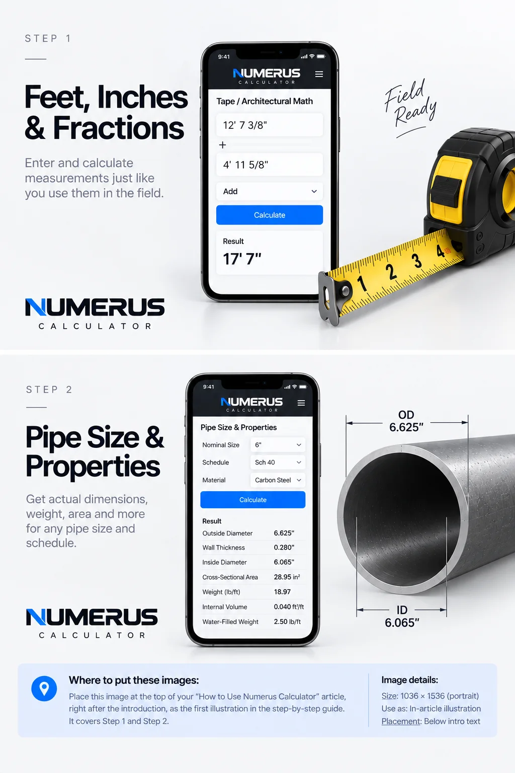
Steps 1–2 — Use Numerus Calculator to work with feet, inches, and fractions, then select the pipe size and schedule to reference actual OD, ID, wall thickness, and other key pipe properties.
Step 4: Calculate a Simple Pipe Offset
Open Simple Offset.
You need two primary inputs:
Offset
Fitting angle
Enter the required offset distance and the angle of the fittings being used.
Numerus calculates the corresponding offset geometry, including travel and advance/setback information.
Example
Suppose a pipe needs to move vertically to clear an obstruction.
The required offset is known, and the spool will use a specific fitting angle.
Enter the measured offset and fitting angle into Numerus.
The calculator develops the geometry needed to lay out the offset.
This becomes particularly helpful when the fitting angle isn’t one of the standard angles you normally calculate from memory.
What You Should Check
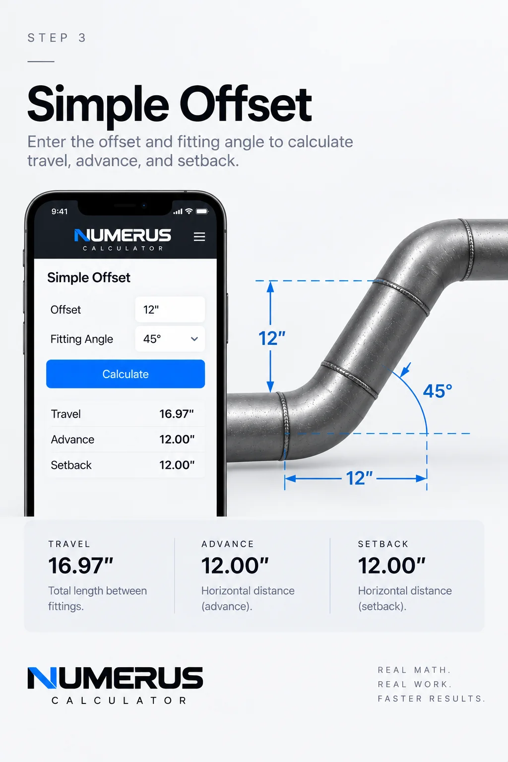
Step 3 — Calculate a simple offset by entering the required offset and fitting angle. Numerus calculates the travel and related geometry needed to lay out the offset.
Before using the answer, confirm:
The offset was measured correctly.
The fitting angle matches the actual fittings.
The takeoffs being used match the actual fittings.
The route has sufficient clearance.
The calculated geometry makes physical sense.
A calculator can solve the triangle.
It cannot see the obstruction you’re trying to miss.
Step 5: Calculate a Rolling Offset
A simple offset moves primarily within one plane.
A rolling offset moves in two.
Open Rolling Offset.
Enter:
Horizontal roll
Vertical roll
Fitting angle
Numerus combines the horizontal and vertical movement to determine the true offset geometry and travel.
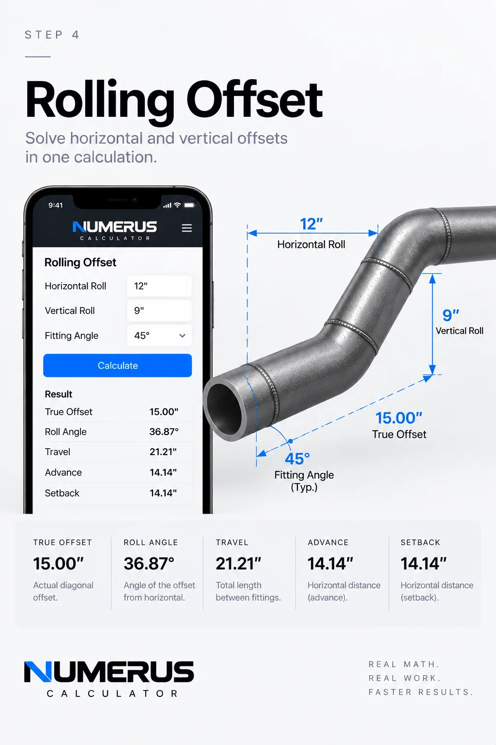
Step 4 — Calculate a rolling offset by entering the horizontal roll, vertical roll, and fitting angle. Numerus combines both directions to determine the true offset, roll angle, travel, and related layout dimensions.
Field Example
Imagine a pipe needs to move:
12 inches horizontally
and
9 inches vertically
The first part of the problem is finding the true offset created by those two movements.
Geometrically:
True Offset = √(Horizontal² + Vertical²)
Numerus handles that calculation and then uses the selected fitting angle to develop the required travel.
This is especially useful when routing piping around structural steel, existing piping, equipment or other obstructions where the destination isn’t directly above, below or beside the starting point.
Field Rule: A rolling offset is two triangles working together. Understand the geometry before trusting the travel.
Step 6: Calculate an Elbow Takeoff
Open Elbow Takeoff.
Enter or select the nominal pipe size and elbow type.
Numerus can calculate theoretical center-to-end dimensions for common long-radius and short-radius 90-degree elbows.
There is also a custom takeoff option.
That is important because the fitting in your hand always outranks the theoretical number on the screen.
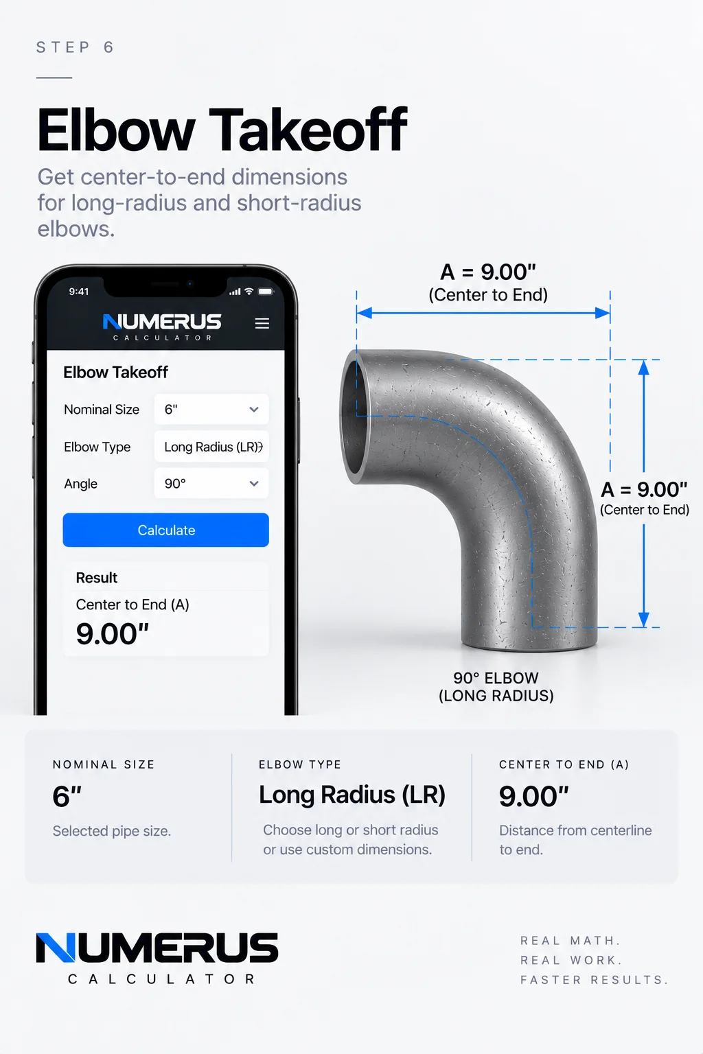
Step 6 — Calculate an elbow takeoff by selecting the nominal pipe size, elbow type, and angle. Numerus provides the theoretical center-to-end dimension for use in pipe layout and spool calculations.
Example
Suppose you’re fabricating a spool with a 90-degree elbow.
Numerus can provide the theoretical takeoff needed for the layout.
Before marking the pipe, verify the actual fitting.
Different fitting types, manufacturers or fabrication conditions may require using an actual measured takeoff instead.
Field Rule: Calculate the fitting. Then measure the fitting.
Step 7: Calculate a Pipe Spool Cut Length
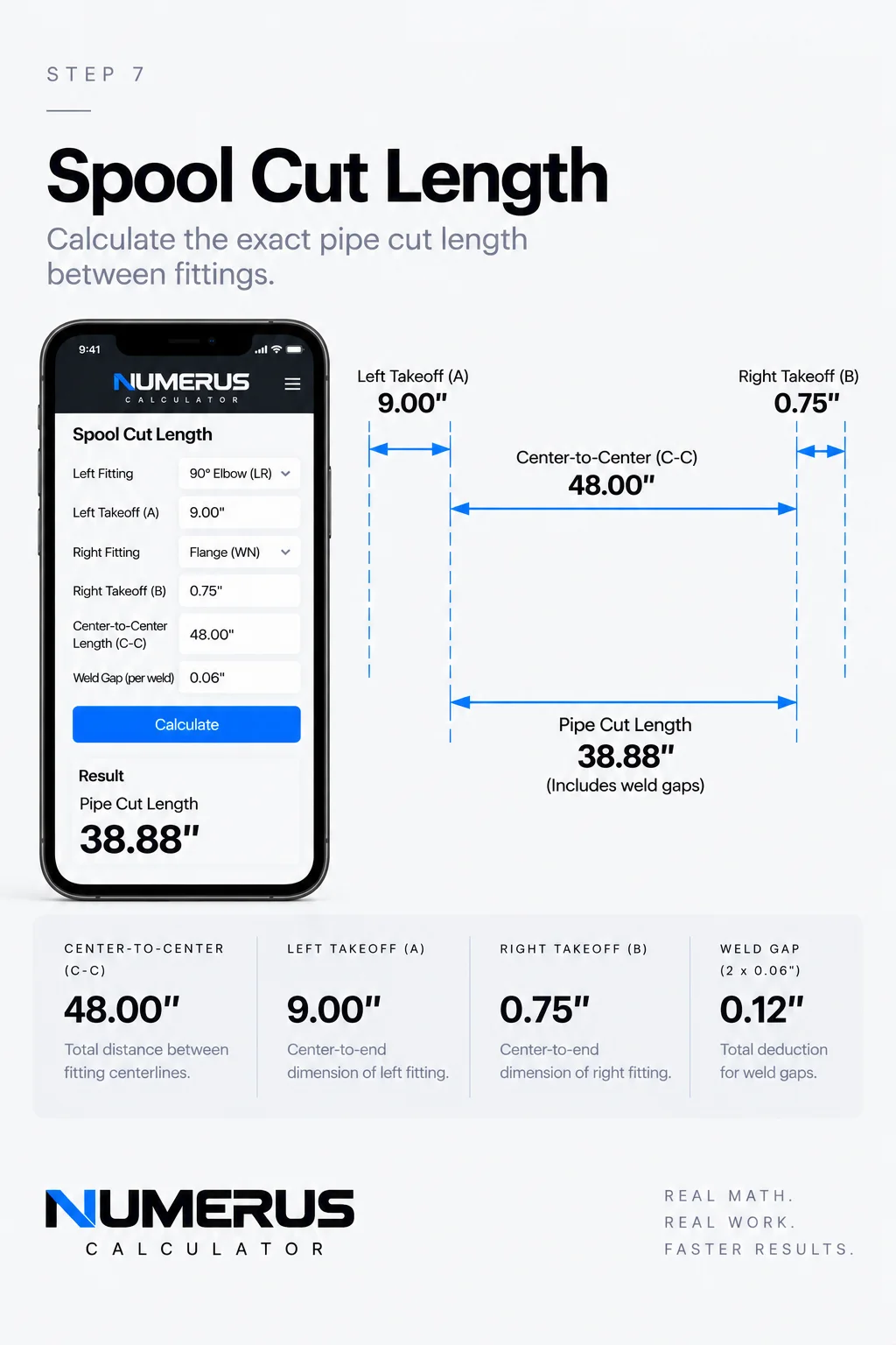
Step 7 — Calculate a spool cut length by entering the center-to-center dimension, fitting takeoffs, weld gaps, and required allowances. Numerus combines the inputs to determine the final pipe cut length before fabrication.
This is one of the most practical Numerus workflows.
Open Pipe Spool Cut-Length Calculator.
You’ll see inputs for:
Overall / C-C dimension
Left fitting takeoff
Right fitting takeoff
Weld gap
Number of gaps
Other allowance
The fundamental calculation is:
Overall Dimension − Left Takeoff − Right Takeoff − Weld Gaps ± Allowances = Pipe Cut Length
Field Example
Imagine you have an overall center-to-center dimension between two fittings.
The spool contains a fitting at each end.
Instead of manually subtracting each fitting takeoff, then accounting for gaps and additional allowances separately, enter each value into Numerus.
The resulting cut length represents the pipe required between those components based on the information entered.
Before Cutting
Check the overall dimension.
Check both fitting takeoffs.
Check the number of weld joints.
Confirm the required root gaps.
Confirm whether any additional allowance should add or subtract length.
Then calculate.
Field Rule: Measure twice. Calculate once. Verify again before cutting.
Step 8: Correct for Weld Gaps
For simpler situations, Numerus also includes Cutback / Weld Gap.
Enter:
Raw cut length
Gap at each joint
Number of gaps
Numerus determines the resulting corrected length.
This is useful when the geometry has already been established and the only remaining adjustment is accounting for multiple joint gaps.
Small corrections matter.
A small dimensional error repeated across several joints can become a much larger fit-up problem by the end of a spool.
Step 9: Calculate Slope and Grade
Open Slope / Grade.
Numerus allows you to work with:
Run
Slope percentage
Fall per foot
This is useful when a drawing gives slope in one format but the field layout needs another.
Example
A piping system may require a specific percentage of slope.
Numerus can translate that requirement into a practical fall per foot.
Once you know the fall per foot, you can determine the required elevation change over the total run.
This is useful for drain piping, gravity systems and other installations where maintaining consistent slope matters.
Field Rule: Always confirm which direction the system is supposed to fall before laying out elevations.
Step 10: Calculate Pipe Spacing
Open Pipe Spacing.
Enter:
Pipe A OD
Pipe B OD
Required clear gap
Numerus determines the centerline spacing required to maintain that clearance.
Why This Matters
Imagine two different pipe sizes running parallel.
The drawing or project requirement calls for a specific clear distance between their outside surfaces.
You can’t simply add the clear distance to one pipe diameter.
Each pipe contributes half of its outside diameter to the centerline-to-centerline measurement.
The basic geometry is:
Centerline Spacing = ½ OD A + Clear Gap + ½ OD B
Numerus performs the calculation automatically.
This can be useful for pipe racks, supports, fabrication assemblies and parallel runs.
Step 11: Work With Tank-Wrap Geometry
Open Tank Wrap / Hexagon.
Enter:
Tank diameter
Required clearance to pipe centerline
Numerus develops the geometry for a regular six-sided route around the circular tank.
This is a more specialized calculation, but it demonstrates why Numerus contains more than everyday arithmetic.
Some calculations aren’t difficult because the math is impossible.
They’re difficult because you may only need them occasionally.
Having the geometry available when you need it can save considerable layout time.
Step 12: Calculate Dummy-Leg and Support Geometry
Open Dummy Leg / Support Geometry.
Enter the horizontal and vertical projections.
Numerus treats the support as right-triangle geometry and solves the resulting length.
The same underlying principle appears repeatedly throughout industrial layout:
Rise² + Run² = Travel²
Understanding that relationship makes offsets, braces, supports and many other field calculations easier to visualize.
Step 13: Calculate a Flange Bolt Circle
Open Flange Bolt Circle.
Enter:
Bolt circle diameter
Number of holes
Starting rotation
Numerus determines the bolt-hole positions around the circle.
This can help visualize and calculate flange orientation when laying out or checking fabricated components.
Remember that bolt-circle geometry must still match the actual flange and project requirements.
Step 14: Convert Flange Rotation Into a Measurement
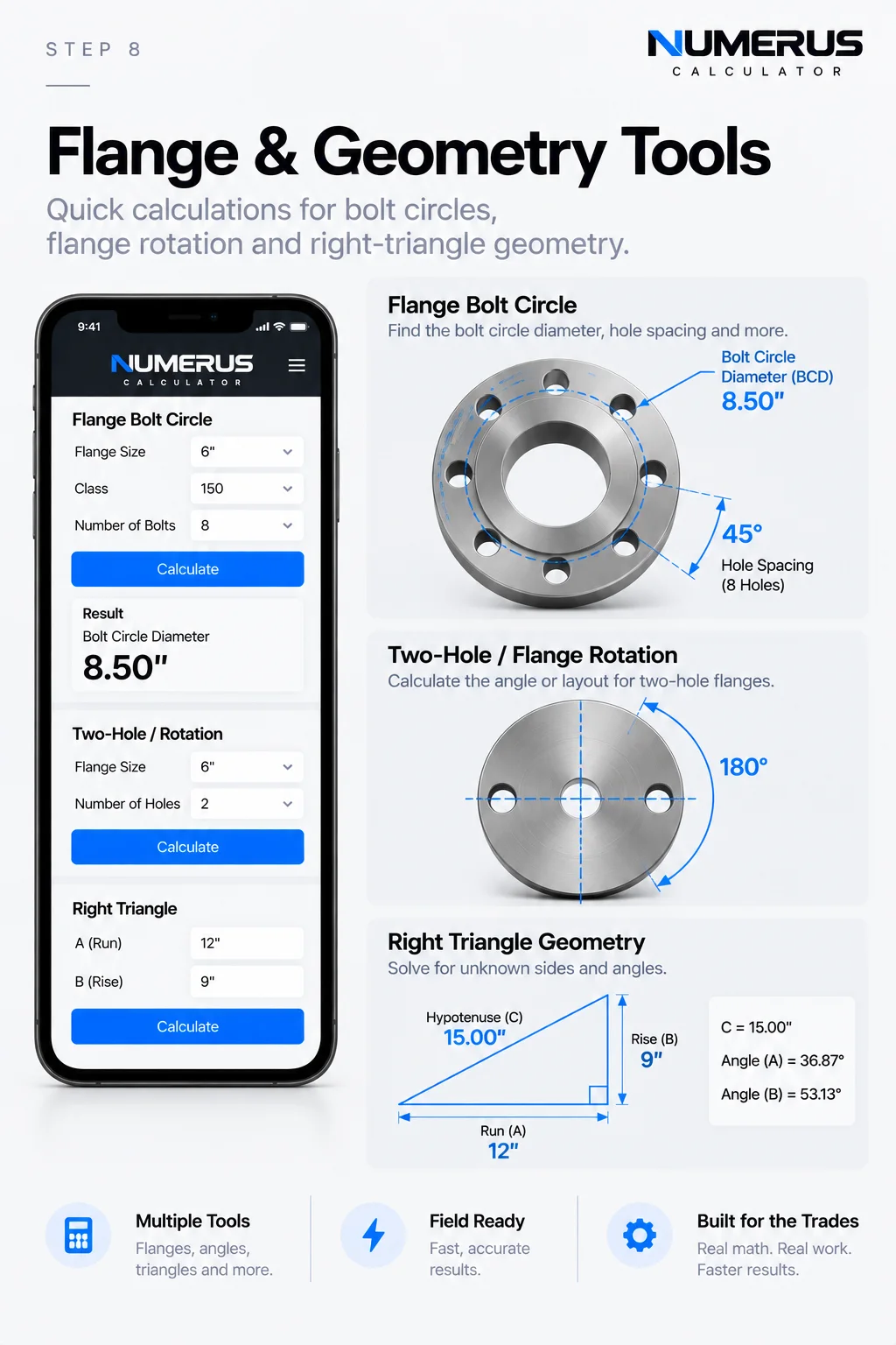
Step 8 — Explore Numerus flange and geometry tools to calculate bolt-circle layouts, flange rotation, and right-triangle dimensions from one field-focused calculator.
Open Two-Hole / Rotation.
Enter:
Bolt circle diameter
Rotation angle
Numerus converts the angular rotation into a linear chord measurement across the bolt circle.
This can make an angular requirement easier to establish using physical measurements.
Instead of thinking only in degrees, you’re translating the rotation into something measurable.
Step 15: Solve Right-Triangle Geometry
Open Right Triangle.
You’ll find:
Rise A
Run B
Hypotenuse C
Enter any two known sides and leave the unknown side blank.
Numerus solves the remaining side.
This calculator extends well beyond piping.
Right triangles appear in structural layout, supports, bracing, fabrication, construction and countless other trade applications.
Learning to recognize the triangle inside a physical problem is one of the most valuable field-math skills you can develop.
Step 16: Calculate Circle, Arc and Chord Geometry
Open Circle / Arc / Chord.
Enter the required diameter, arc angle and divisions.
Numerus calculates the associated circular geometry.
This becomes useful when laying out positions around a circumference, dividing circular components or converting degrees into physical distances.
If you’re learning this type of layout, the Næxon article Saddle Pipe Layout: Circumference and Degrees provides a practical introduction to thinking about a pipe circumference in degrees.
Step 17: Calculate Flow From Pipe ID and Velocity
Open Flow from ID & Velocity.
Enter:
Inside diameter
Velocity
Numerus calculates the resulting flow.
Notice that this calculation uses inside diameter, not nominal size or outside diameter.
That’s another example of why understanding what a calculator is asking for matters.
OD describes the outside of the pipe.
ID describes the available internal flow diameter.
They are not interchangeable.
Step 18: Convert Pressure Into Force
Open Pressure → Force.
Enter:
Pressure in psi
Area in square inches
Numerus calculates the resulting force.
The underlying relationship is:
Force = Pressure × Area
This simple equation helps explain why pressure acting over larger areas can generate extremely large forces.
Treat pressure calculations with respect and follow applicable engineering, testing and safety procedures.
Step 19: Calculate Pipe Hydrostatic Content
Open Pipe Hydrostatic Content.
Enter:
Inside diameter
Pipe length
Numerus calculates the internal content associated with that section of pipe.
This can help provide a better understanding of how much fluid a piping system actually contains.
For field operations involving hydrostatic testing, calculations should always be used alongside approved procedures, engineering requirements and site safety rules.
Step 20: Convert Industrial Units
Open Industrial Unit Conversions.
Choose the measurement category.
Select the starting unit.
Select the destination unit.
Enter the value.
Then convert.
This is particularly useful when drawings, specifications, equipment information or manufacturer documentation use different measurement systems.
Step 21: Generate Pipe Saddle and Lateral Patterns
Numerus also contains a Pipe Saddle / Lateral Pattern Generator.
Enter information such as:
Branch OD
Header OD
Branch angle
Centerline offset
Axial cut allowance
Ordinate divisions
Numerus can generate a developed pattern, ordinate information and SVG output.
For dedicated saddle and lateral development, however, Næxon also offers Rapit Pro.
Rapit Pro is specifically designed around the complete saddle-pattern workflow, including centered and offset intersections, connection geometry, pattern development, fabrication references and printable templates.
If saddle development is the main job, use Rapit Pro.
If you’re moving between many different types of trade calculations, Numerus gives you the broader toolbox.
A Faster Numerus Workflow
Once you become familiar with the calculator, the process becomes simple:
Identify the field problem → Select the correct Numerus tool → Enter the known measurements → Calculate → Check the geometry → Verify against the drawing and actual material → Proceed with layout or fabrication.
The important part isn’t pressing the Calculate button.
It’s everything surrounding it.
Common Mistakes to Avoid
Using Nominal Size Instead of Actual OD
If the calculator asks for outside diameter, enter outside diameter.
Nominal pipe size is not automatically the physical outside measurement.
Entering the Wrong Type of Dimension
Center-to-center, face-to-face, overall, takeoff and cut length describe different dimensions.
Make sure the number you’re entering represents what the calculator expects.
Forgetting Weld Gaps
A spool containing several joints may accumulate enough gap to affect the final cut length.
Using Theoretical Fitting Dimensions Without Verification
Numerus can calculate theoretical fitting geometry.
The fitting in your hand should still be measured when accuracy matters.
Rounding Too Early
Keep sufficient precision through intermediate calculations and round the final usable measurement when appropriate.
Trusting an Answer You Don’t Understand
This is the biggest one.
If Numerus gives you a travel dimension that physically looks impossible, stop.
Check the inputs.
Check the units.
Check the geometry.
Then calculate again.
Field Rule: The calculator should confirm your thinking—not replace it.
Numerus and Rapit Pro
Næxon now has two tools designed for different parts of industrial field math.
Numerus Calculator is the broad trade-math platform.
Use it for measurements, fractions, pipe properties, offsets, fitting takeoffs, spool cut lengths, slope, spacing, flange geometry, triangles, conversions and other calculations.
Rapit Pro is the specialized pipe-pattern platform.
Use it when you need to develop a saddle or lateral connection and create a printable pattern for fabrication.
Together, the goal is simple:
Spend less time repeating calculations and more time understanding, checking and performing the work.
Knowledge Check
1. If a calculation asks for pipe OD, should you automatically enter the nominal pipe size?
No. Use the actual outside diameter required by the calculation.
2. What three inputs are central to a rolling-offset calculation?
Horizontal roll, vertical roll and fitting angle.
3. What should be subtracted from an overall spool dimension when calculating pipe cut length?
Applicable fitting takeoffs, weld gaps and other required dimensional corrections.
4. Why should an elbow takeoff still be checked after Numerus calculates it?
Because the actual fitting or fabrication condition may differ from the theoretical dimension.
5. What should you do if a calculated answer doesn’t physically make sense?
Stop and verify the inputs, units, dimensions and geometry before using the result.
Practical Exercise
Open Numerus Calculator and complete the following exercise.
Start with a simple field measurement using feet, inches and fractions.
Then solve a basic pipe offset.
Next, create a rolling offset using different horizontal and vertical movements.
Calculate an elbow takeoff.
Use that takeoff as part of a spool cut-length problem.
Finally, open the right-triangle calculator and compare the geometry with the offset calculations you completed earlier.
The objective isn’t simply to get five answers.
Look at how the calculations connect.
Offsets are triangles.
Rolling offsets combine triangles.
Takeoffs affect spool lengths.
Pipe OD affects spacing and circular geometry.
Flange rotation converts angular movement into measurable geometry.
Once those relationships become familiar, Numerus stops being a collection of calculators.
It becomes a faster way to work through math you already understand.
Always verify calculated dimensions against approved drawings, actual material, manufacturer data, project specifications, applicable procedures and field conditions before fabrication, testing or installation.