Steam turbines are among the most important pieces of rotating equipment in a refinery.
They can drive pumps, compressors, generators, and other critical machinery by converting the energy contained in high-pressure steam into mechanical rotation.
The basic principle is:
High-Pressure Steam → Turbine → Shaft Rotation → Driven Equipment
After transferring part of its energy to the turbine:
Lower-Pressure Steam → Exhaust System
A steam turbine can look relatively simple from the outside—a steel casing, steam piping, shaft, bearings, and coupling. Inside, however, steam may be moving through precisely engineered nozzles and blades at extremely high velocity while the rotor spins at thousands of revolutions per minute.
For pipefitters, millwrights, operators, welders, machinists, instrument technicians, electricians, inspectors, and refinery maintenance personnel, understanding steam turbines means understanding the relationship between steam pressure, temperature, speed, lubrication, vibration, alignment, thermal expansion, condensate, and overspeed protection.
What Is a Steam Turbine?

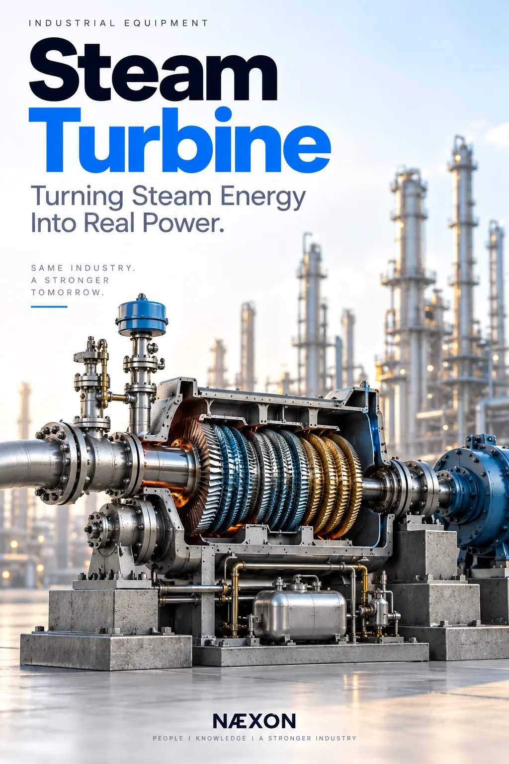
Figure: Cutaway view of a refinery steam turbine showing high-pressure steam entering through the trip and control valves, expanding across stationary and rotating blades to turn the rotor, and exiting at lower pressure while shaft power is transferred through the coupling to the driven equipment.
A steam turbine is a rotating machine that converts the thermal and pressure energy of steam into mechanical energy.
Steam enters the turbine at relatively high pressure and temperature.
Inside the turbine, steam expands through stationary and rotating components.
As the steam expands, its pressure and temperature decrease while its velocity changes.
That energy produces force on the turbine blades.
The blades are connected to the rotor.
The rotor turns.
That rotating shaft can then drive another machine.
The process is:
Steam Energy → Blade Force → Rotor Rotation → Shaft Power
Why Refineries Use Steam Turbines
Refineries generate and distribute large quantities of steam.
Steam is used for:
- Process heating
- Stripping
- Reboilers
- Tracing
- Ejectors
- Turbine drivers
- Other process and utility services
Instead of using electricity for every rotating machine, some refinery equipment can use steam turbines.
A turbine may drive:
- Centrifugal pumps
- Process compressors
- Boiler feedwater pumps
- Cooling-water pumps
- Fans
- Generators
Steam turbines are particularly valuable where a refinery already has a sophisticated steam system with multiple pressure levels.
The Basic Steam Turbine Process
A simplified turbine system looks like:
High-Pressure Steam Header
↓
Isolation / Trip / Control Valves
↓
Steam Turbine
↓
Rotor Spins
↓
Coupling
↓
Pump or Compressor
Meanwhile:
Lower-Pressure Exhaust Steam
↓
Lower-Pressure Steam Header or Condenser
The steam and driven equipment are mechanically connected through the turbine shaft, but the process fluid handled by the pump or compressor remains separate from the steam system.
The Energy Conversion
To understand a turbine, imagine steam stored at high pressure.
That steam contains usable energy.
When it passes through specially shaped stationary passages or nozzles, pressure energy is converted into high steam velocity.
The high-velocity steam interacts with turbine blades.
That creates force on the rotor.
Conceptually:
Pressure Energy
↓
Steam Velocity
↓
Blade Force
↓
Rotor Torque
↓
Shaft Rotation
That is the heart of turbine operation.
1. Steam Inlet
High-pressure steam enters through the turbine inlet piping.
Depending on the refinery steam system, the inlet steam may be:
- High pressure
- Superheated
- Extremely hot
- Traveling through large insulated piping
The inlet connection leads steam toward the turbine’s valve and steam-chest arrangement.
Steam quality at this point matters enormously.
2. Steam Chest
The steam chest receives steam before it enters the turbine stages.
Steam admission is controlled by valves.
These valves determine how much steam enters the machine.
More steam generally means more available turbine power.
Less steam reduces turbine output.
This provides the foundation for turbine speed and load control.
3. Trip Valve
One of the most important components in the steam path is the trip valve, sometimes called a stop valve depending on the turbine design.
Its job is simple but critical:
Stop steam from entering the turbine when a protective trip occurs.
If the turbine experiences a dangerous condition, the protection system must rapidly remove the energy source.
Closing the steam supply is how that happens.
4. Governor / Control Valve
The turbine needs to maintain the required speed.
A governor or electronic control system monitors speed and adjusts steam admission.
Conceptually:
Speed Too Low → More Steam
Speed Too High → Less Steam
The control valve continuously regulates steam flow to maintain the desired operating condition.
Modern refinery turbines may use sophisticated electronic control systems, but the basic principle remains the same.
5. Turbine Casing
The casing surrounds the internal steam path.
It forms the pressure-containing boundary around the turbine internals.
The casing must withstand:
- Steam pressure
- High temperature
- Thermal expansion
- Internal forces
- Operating cycles
Many turbine casings are split horizontally so the upper half can be removed during major maintenance.
This gives maintenance crews access to the rotor and internal components.
6. Rotor
The rotor is the rotating heart of the turbine.
It consists of a shaft carrying the rotating turbine elements.
The rotor transfers mechanical energy from the steam path to the driven equipment.
A simplified arrangement is:
Steam → Blades → Rotor → Shaft → Coupling → Pump
The rotor must remain precisely balanced.
At high rotational speed, very small mechanical imperfections can produce significant vibration.
7. Turbine Blades
Turbine blades interact with the steam.
Depending on turbine design, there may be:
- Stationary blades
- Rotating blades
- Nozzles
- Multiple stages
The stationary components direct steam.
The rotating blades extract energy from it.
The geometry is engineered carefully to convert steam energy efficiently into rotation.
Stationary vs. Rotating Blades
A turbine stage may include stationary and rotating components.
Stationary Components
These redirect or accelerate the steam toward the next rotating row.
Rotating Blades
These receive force from the steam and transfer that energy into the rotor.
The process can repeat through several stages.
Stationary → Rotating → Stationary → Rotating
As steam moves through the turbine, more energy can be extracted.
Single-Stage Turbines
Smaller refinery turbines may use a relatively simple single-stage design.
These are commonly found driving equipment such as pumps.
The turbine can be compact and mechanically straightforward.
Even a small turbine, however, can operate at very high rotational speed.
Never confuse physical size with stored mechanical energy.
Multistage Turbines
Larger turbines may contain multiple stages.
Instead of extracting the steam’s available energy in one step, the turbine does it progressively.
High-Pressure Steam
↓
Stage 1
↓
Stage 2
↓
Stage 3
↓
Lower-Pressure Exhaust Steam
Multistage designs can achieve higher efficiency and handle larger power requirements.
Impulse Turbines
In an impulse turbine, steam expands primarily through stationary nozzles.
The nozzles convert pressure into velocity.
High-velocity steam then strikes or passes across the rotating blades.
The change in steam momentum produces rotor torque.
Simplified:
Steam Pressure → Nozzle → High Velocity → Rotor Blade → Rotation
Reaction Turbines
In a reaction turbine, steam expansion occurs through both stationary and rotating blade passages.
The pressure continues changing as steam moves through the rotor blades.
Large industrial turbines may use reaction principles or combinations of turbine staging concepts depending on design.
For field workers, the important point is that the internal blade arrangement is engineered specifically for the machine.
Internal components are not interchangeable simply because they look similar.
Exhaust Steam
After passing through the turbine, steam exits at a lower pressure.
Where it goes depends on turbine design.
Two major arrangements are:
Backpressure turbines
and
Condensing turbines.
Backpressure Turbine
A backpressure turbine exhausts steam into a lower-pressure steam system.
For example:
High-Pressure Steam → Turbine → Medium-Pressure Steam Header
or:
Medium-Pressure Steam → Turbine → Low-Pressure Steam Header
The refinery gets two benefits:
Mechanical shaft power
and
Useful lower-pressure steam
This can make backpressure turbines very efficient within an integrated refinery steam system.
Condensing Turbine
A condensing turbine exhausts steam into a condenser operating at very low pressure.
The steam is condensed back into water.
This allows the turbine to extract more energy from the steam because the exhaust pressure is much lower.
A simplified arrangement is:
High-Pressure Steam → Turbine → Low-Pressure Exhaust → Condenser → Condensate
Condensing turbines require additional equipment and systems.
The Coupling
The turbine shaft must transfer rotation to the driven equipment.
This is accomplished through a coupling.
The coupling connects:
Turbine Shaft ↔ Driven Equipment Shaft
The driven machine might be a:
- Pump
- Compressor
- Generator
- Fan
Coupling alignment is extremely important.
Alignment
Turbine and driven-equipment shafts must be precisely aligned.
Poor alignment can cause:
- Excessive vibration
- Bearing loads
- Coupling damage
- Seal problems
- Shaft problems
- Reduced equipment life
Alignment must also consider operating temperature.
A turbine may move as it heats.
The cold alignment condition may therefore intentionally differ from the final hot operating position.
Thermal Growth
A turbine casing becomes much hotter during operation than during shutdown.
Metal expands when heated.
Therefore:
Cold Turbine ≠ Hot Turbine Dimensions
The casing and shaft can grow as temperature rises.
The foundation, supports, piping, coupling alignment, and casing guides must accommodate this movement.
Why Pipefitters Need to Understand Thermal Growth
Steam piping connected to a turbine can exert enormous force if incorrectly installed.
A turbine nozzle should not be used as an anchor point to pull misaligned piping into position.
Poor piping alignment can create:
Pipe Stress → Nozzle Load → Casing Distortion → Shaft Misalignment → Vibration
This is why turbine piping alignment is taken so seriously.
Bearings
The rotor is supported by bearings.
Common turbine bearing functions include:
Journal Bearings
Support the radial weight and forces of the rotor.
Thrust Bearing
Controls axial rotor position.
Steam forces can push the rotor along its shaft axis.
The thrust bearing prevents excessive axial movement.
Thrust Position
Axial rotor position can be extremely important.
If the rotor moves too far axially, internal clearances may be lost.
This can allow rotating and stationary components to contact.
Large turbines may therefore monitor thrust position continuously.
Abnormal axial movement can trigger alarms or trips.
Lubrication System
Bearings require reliable lubrication.
The lube-oil system may include:
- Oil reservoir
- Main oil pump
- Auxiliary oil pump
- Emergency oil supply
- Oil coolers
- Filters
- Pressure controls
- Temperature monitoring
Lubricating oil creates a protective film between moving surfaces.
Loss of that film can rapidly damage bearings.
Why Lube Oil Is Critical
A turbine rotor may be spinning thousands of times every minute.
If lubrication is lost:
Oil Film Fails
↓
Metal Contact Increases
↓
Bearing Temperature Rises
↓
Bearing Damage
↓
Potential Rotor Damage
This can happen quickly.
Low lube-oil pressure is therefore commonly an important protective trip condition.
Auxiliary Oil Pump
Some systems use an auxiliary oil pump during startup, shutdown, or low-pressure conditions.
Before the main rotor reaches operating conditions, reliable oil pressure must already exist.
The auxiliary pump ensures the bearings receive lubrication before and during critical transitions.
Bearing Temperature
Bearing temperature is monitored because abnormal temperature can indicate:
- Lubrication problems
- Misalignment
- Excessive load
- Bearing damage
- Cooling problems
A rising bearing temperature should never be dismissed as simply “running hot.”
It can be an early warning of mechanical failure.
Vibration
Vibration is one of the most important indicators of rotating-equipment condition.
Potential causes include:
- Rotor imbalance
- Misalignment
- Bearing problems
- Mechanical looseness
- Steam-path damage
- Coupling problems
- Foundation problems
- Piping strain
- Rotor rub
- Deposits
Large turbines may have continuous vibration monitoring.
Rotor Imbalance
The turbine rotor must remain balanced around its rotational axis.
If mass becomes unevenly distributed, centrifugal forces increase with speed.
The result can be severe vibration.
Even a relatively small imbalance can become significant at high RPM.
Critical Speed
Every rotating system has natural frequencies.
At certain rotational speeds, rotor excitation can approach one of those natural frequencies.
This region is called a critical speed.
During startup, some turbines are designed to accelerate through critical-speed ranges promptly according to the operating procedure rather than remain there.
The reason:
Resonance can greatly amplify vibration.
Shaft Seals
The turbine shaft passes through the casing.
There must therefore be a way to limit steam leakage around the shaft.
Turbines use sealing systems such as labyrinth seals and gland arrangements.
These allow rotation while restricting steam leakage.
Gland Steam
Some turbines use gland steam systems.
The exact function depends on turbine location and pressure conditions.
Gland steam can help control leakage and prevent unwanted air entry into low-pressure portions of condensing turbines.
The system may include:
- Seal steam supply
- Leak-off connections
- Gland condenser
- Control valves
Steam Drains
Steam piping and turbine casings can collect condensate.
This water must be managed carefully.
Drains may be installed at low points in:
- Steam piping
- Steam chest
- Turbine casing
- Other applicable locations
During warm-up, drains may be opened according to operating procedures to remove condensate.
Why Water Is Dangerous to a Steam Turbine
Steam is compressible vapor.
Water is a dense liquid.
Turbine blades designed for steam can be severely damaged if significant liquid water enters at high velocity.
Potential consequences include:
- Blade erosion
- Mechanical shock
- Vibration
- Internal damage
This is why proper steam-line warming and condensate removal are so important.
Water Hammer
Condensate trapped in steam piping can also contribute to water hammer.
High-velocity steam can accelerate liquid slugs through the piping.
When the liquid suddenly changes direction or impacts an obstruction:
Momentum → Impact Force
The resulting forces can damage:
- Piping
- Supports
- Valves
- Flanges
- Equipment nozzles
Steam systems must be warmed and drained according to procedure.
Steam Traps
Steam traps automatically remove condensate while minimizing the loss of live steam.
They are common throughout refinery steam systems.
A properly operating trap helps keep steam lines and equipment free of accumulated condensate.
A failed trap can create operating problems.
Warm-Up
A cold turbine should not simply be exposed instantly to full operating-temperature steam.
Rapid heating can create uneven thermal expansion.
Controlled warm-up allows the casing, piping, valves, and rotor system to heat more gradually.
Startup procedures may control:
- Steam admission
- Drain positions
- Speed
- Temperature
- Vibration
- Expansion
The exact sequence is turbine-specific.
Turning Gear
Large steam turbines may use a turning gear or barring system.
After shutdown, a hot rotor left stationary can cool unevenly and bow.
The turning gear slowly rotates the rotor during cooling.
This promotes more uniform temperature distribution.
Not every refinery turbine uses one, but it is important on larger machines.
Speed Control
Turbine speed directly determines the speed of the driven equipment unless a gearbox or other arrangement changes the relationship.
The control system therefore regulates steam flow to maintain required RPM.
For a turbine-driven pump:
More Steam → More Turbine Torque → Potentially More Pump Speed
depending on the control arrangement.
Overspeed
One of the most dangerous turbine conditions is overspeed.
If load suddenly disappears while steam continues entering the turbine, the rotor can accelerate rapidly.
Example:
Turbine Driving Pump
↓
Coupling or Load Lost
↓
Steam Still Entering
↓
Rotor Accelerates
If uncontrolled, rotor speed could exceed safe mechanical limits.
Overspeed Trip
Steam turbines therefore have independent overspeed protection.
If speed exceeds the trip threshold, the system rapidly closes steam admission.
The basic protection is:
Excessive RPM → Overspeed Trip → Steam Valve Closes → Turbine Decelerates
Overspeed protection is one of the turbine’s most critical safety systems.
It must be maintained and tested according to approved procedures.
Other Turbine Trip Conditions
Depending on the turbine, protective trips may include:
- Overspeed
- Low lube-oil pressure
- High vibration
- High bearing temperature
- Excessive axial displacement
- Low condenser vacuum
- Other machine-specific conditions
A trip exists to protect equipment and potentially personnel.
Never bypass turbine protection without formally approved procedures.
Emergency Trip
Turbines commonly provide a means for rapid shutdown.
Activating the emergency trip removes steam admission by closing the trip valve.
Workers around turbine equipment should know the location and function of emergency controls according to site requirements.
Turbine-Driven Pump
One of the most common refinery arrangements is:
Steam Turbine → Coupling → Centrifugal Pump
The turbine replaces an electric motor as the pump driver.
You may see both systems in the same service:
Pump A — Electric Motor
Pump B — Steam Turbine
This can provide operational flexibility.
Why Have Electric and Steam Drivers?
Using different driver types can improve resilience.
For example, certain disturbances may affect electrical power while steam remains available.
Conversely, steam-system problems may affect the turbine while an electric driver remains available.
The exact redundancy philosophy depends on refinery design.
Turbine-Driven Compressor
Large process compressors may also use steam turbines.
In this case the turbine can be substantially larger and more complex.
The system may include:
- Multistage turbine
- Compressor
- Large lube-oil system
- Seal system
- Condenser
- Control system
- Extensive vibration monitoring
These machines can be among the most critical rotating-equipment trains in the refinery.
Governor Problems
A turbine governor or control system must respond smoothly to changing load.
Problems can result in:
- Speed instability
- Hunting
- Poor load response
- Inability to maintain RPM
Control valves, actuators, instrumentation, and control logic can all influence performance.
Steam Valve Problems
Steam valves operate under severe temperature and pressure conditions.
Potential issues include:
- Sticking
- Leakage
- Erosion
- Deposits
- Actuator problems
- Seat damage
A trip valve that cannot close properly represents a serious protection concern.
Steam Leakage
External steam leaks can be extremely dangerous.
High-pressure steam may be difficult to see clearly.
A small high-pressure leak can create a high-velocity jet capable of causing severe injury.
Never search for steam leaks with your hands.
Suspected leaks must be handled under site procedures.
Insulation
Turbines and steam piping are often heavily insulated.
Insulation:
- Reduces heat loss
- Protects personnel
- Helps maintain process temperature
- Controls external surface temperatures
Damaged or missing insulation can expose extremely hot surfaces.
Turbine Exhaust Piping
Exhaust piping can be very large.
Because the exhaust steam may be lower pressure, its specific volume can be much greater than at the inlet.
The piping must also accommodate thermal expansion.
Poor exhaust-piping support can transfer significant loads into the turbine casing.
Condenser and Vacuum
A condensing turbine may exhaust into a surface condenser.
Cooling water removes heat from the exhaust steam and condenses it.
Condensing steam dramatically reduces volume and helps create low pressure at the turbine exhaust.
Maintaining condenser performance is therefore directly related to turbine performance.
Why Vacuum Matters
Lower exhaust pressure allows the turbine to extract more energy from the steam.
If condenser vacuum deteriorates, turbine efficiency and available power can decrease.
Severe vacuum problems may require protective action depending on the machine.
Common Steam Turbine Problems
Workers may encounter:
- High vibration
- Bearing overheating
- Low oil pressure
- Steam leakage
- Seal leakage
- Governor instability
- Valve sticking
- Rotor imbalance
- Misalignment
- Excessive thrust movement
- Water induction
- Blade erosion
- Fouling or deposits
- Piping strain
- Condenser problems
- Steam-trap failures
Troubleshooting should consider the turbine as a complete system rather than only the rotating casing.
Turnaround Inspection
During major maintenance, the turbine may be opened for inspection.
Depending on scope, crews may inspect:
- Casing
- Rotor
- Shaft
- Blades
- Nozzles
- Diaphragms
- Bearings
- Thrust bearing
- Seals
- Coupling
- Control valves
- Trip valve
- Oil system
- Steam chest
- Exhaust components
Clearances may be measured and compared with manufacturer requirements.
Removing the Upper Casing
On horizontally split turbines, the upper casing may be lifted during an overhaul.
This is a precision lift.
The casing must clear:
- Studs
- Internal components
- Rotor
- Sealing surfaces
Rigging, lift points, balance, and vertical movement are carefully controlled.
Damage to a machined joint surface can create significant problems during reassembly.
Rotor Removal
Removing a turbine rotor requires extremely careful rigging.
The rotor can be:
- Heavy
- Long
- Precisely machined
- Easily damaged
- Expensive
The shaft journals and blades must be protected.
Rotor lifting devices and procedures are typically engineered specifically for the machine.
Foreign-Material Exclusion
When a turbine is open, foreign-material exclusion becomes extremely important.
A small object left inside can become catastrophic when the machine reaches operating speed.
Tools, hardware, rags, measuring equipment, and temporary materials must be carefully controlled.
Turbine Alignment After Maintenance
After reassembly, alignment between the turbine and driven machine may be checked.
This can involve extremely small tolerances.
Workers must consider:
- Shaft centerline
- Coupling condition
- Soft foot
- Thermal growth
- Piping loads
- Foundation condition
Alignment is not simply making two shafts appear straight.
Piping Strain
A properly aligned turbine can become misaligned after process piping is connected if the piping applies excessive force.
This is called piping strain.
A good installation requires the piping to meet the equipment naturally within specified tolerances.
Never use flange bolts as a pulling tool to force turbine piping into place.
What Pipefitters Should Recognize
When approaching a steam turbine, identify:
- Steam inlet
- Main steam isolation
- Trip valve
- Control/governor valve
- Turbine casing
- Exhaust
- Steam drains
- Gland/seal connections
- Lube-oil piping
- Turbine shaft
- Coupling
- Driven equipment
- Supports
Then determine:
Where does the high-pressure steam come from?
Where does the exhaust steam go?
What equipment is the turbine driving?
Those three questions explain the basic system.
What Millwrights Should Recognize
Millwrights should understand the relationship among:
- Rotor
- Bearings
- Coupling
- Alignment
- Vibration
- Thermal growth
- Shaft seals
- Lubrication
- Driven equipment
A turbine problem may actually originate from the pump, compressor, coupling, foundation, or piping.
Always think in terms of the complete equipment train.
Steam Turbine vs. Electric Motor
Both can drive rotating equipment.
Electric Motor
Electrical Energy → Rotation
Steam Turbine
Steam Energy → Rotation
The pump or compressor may perform essentially the same process function regardless of driver.
What changes is the energy source and supporting systems.
Steam Turbine vs. Gas Turbine
A steam turbine uses externally generated steam.
A gas turbine burns fuel and uses hot combustion gases directly through the turbine.
Therefore:
Steam Turbine → Steam
Gas Turbine → Combustion Gas
They share some rotating-equipment principles but are fundamentally different machines.
Important Terminology
Rotor — Rotating shaft assembly.
Casing — Pressure-containing outer body.
Nozzle — Stationary component that directs or accelerates steam.
Blade — Component that interacts with steam to produce or redirect force.
Governor — System controlling turbine speed or load.
Trip Valve — Rapidly shuts off steam during a protective trip.
Journal Bearing — Supports radial rotor loads.
Thrust Bearing — Controls axial rotor position.
Gland Seal — Restricts steam leakage around the shaft.
Backpressure Turbine — Exhausts into a lower-pressure steam system.
Condensing Turbine — Exhausts into a condenser operating at low pressure.
Critical Speed — Speed range associated with a rotor-system natural frequency.
Overspeed — Rotor speed exceeding acceptable limits.
Turning Gear — Slowly rotates certain large turbine rotors during shutdown conditions.
What Every Refinery Worker Should Visualize
When you see a steam turbine driving a pump, picture:
High-Pressure Steam →
enters the steam chest.
↓
Control Valve
regulates flow.
↓
Nozzles / Stationary Blades
direct the steam.
↓
Rotating Blades
receive the steam’s force.
↓
Rotor Spins
↓
Coupling Spins
↓
Pump Spins
Meanwhile:
Lower-Pressure Steam → Exhaust
That is the complete energy path.
Field Rules
When working around steam turbines:
- Treat steam piping as hot and pressurized until isolation is proven.
- Follow approved lockout/tagout and equipment-isolation procedures.
- Verify steam, condensate, oil, and other energy sources before maintenance.
- Never place hands near suspected high-pressure steam leaks.
- Follow prescribed warm-up and drain procedures.
- Never casually change turbine piping supports.
- Do not force steam piping into turbine nozzle alignment.
- Protect machined flange and casing surfaces.
- Maintain strict foreign-material exclusion during open-turbine work.
- Protect rotor journals and blades during maintenance.
- Follow approved shaft-alignment procedures.
- Never modify governor, trip, overspeed, vibration, or lubrication protection without authorization.
- Confirm coupling guards are installed before operation.
- Keep personnel clear of rotating equipment.
- Treat abnormal vibration, bearing temperature, and oil-pressure conditions seriously.
- Follow manufacturer, engineering, operating, and site-specific procedures when returning the machine to service.
Knowledge Check
- What form of energy does a steam turbine convert into mechanical rotation?
- What controls the amount of steam entering the turbine?
- What is the purpose of the trip valve?
- What does the rotor do?
- What is the difference between stationary and rotating turbine blades?
- What is the difference between a backpressure and condensing turbine?
- What does a journal bearing support?
- What does a thrust bearing control?
- Why is lubrication critical?
- Why can condensate entering a turbine be dangerous?
- What is turbine overspeed?
- Why is an overspeed trip critical?
- Why must turbine piping be properly aligned?
- What is thermal growth?
- Why is vibration closely monitored?
Practical Field Exercise
Find a steam-turbine-driven pump or compressor on an approved refinery drawing.
Start at the steam supply and trace:
Steam Header
↓
Isolation Valve
↓
Trip / Control Valve
↓
Steam Turbine
↓
Exhaust
Then trace the mechanical path:
Turbine Rotor → Coupling → Driven Equipment
Next locate:
- Steam drains
- Lube-oil system
- Bearings
- Exhaust piping
- Governor/control system
- Vibration monitoring
- Coupling guard
- Turbine supports
Now ask:
What happens if the driven equipment suddenly stops resisting the turbine while steam continues entering?
The rotor can accelerate.
That is why overspeed protection exists.
Then ask:
What happens if lubrication disappears while the rotor is spinning?
The bearing oil film can fail, rapidly threatening the bearings and rotor.
Those two scenarios explain why overspeed protection and lubrication are among the most important turbine systems to understand.
Final Takeaway
A steam turbine takes energy already available in the refinery’s steam system and turns it into useful mechanical power.
The fundamental energy path is:
High-Pressure Steam → Controlled Expansion → Turbine Blades → Rotor → Coupling → Pump or Compressor
But reliable turbine operation depends on much more than steam.
It requires:
Clean, properly conditioned steam.
Reliable lubrication.
Correct alignment.
Controlled thermal expansion.
Healthy bearings.
Low vibration.
Effective drains.
Reliable trip protection.
And one protection system stands above nearly everything else:
Overspeed protection.
The easiest field concept to remember is:
Steam enters. Energy is extracted. The rotor turns. The pressure drops. The exhaust leaves.
Once you can trace both the steam path and the mechanical power path, a steam turbine stops looking like another insulated machine beside a pump—and starts making sense as one of the refinery’s most important mechanical drivers.