A refinery heat exchanger may not be as visually imposing as a distillation tower or fired heater, but it is one of the most important pieces of equipment in a process unit.
Refineries move enormous amounts of heat.
One process stream needs to be cooled. Another needs to be heated. Instead of wasting that energy, heat exchangers allow heat from one fluid to transfer into another—often without the two fluids ever physically mixing.
They are everywhere: crude units, hydrocrackers, hydrotreaters, catalytic reformers, alkylation units, sulfur units, utilities, compressor systems, tank systems, and countless other services.
For pipefitters, welders, boilermakers, millwrights, operators, inspectors, and maintenance personnel, heat exchangers are equipment you will encounter repeatedly throughout an industrial career.
What Is a Heat Exchanger?
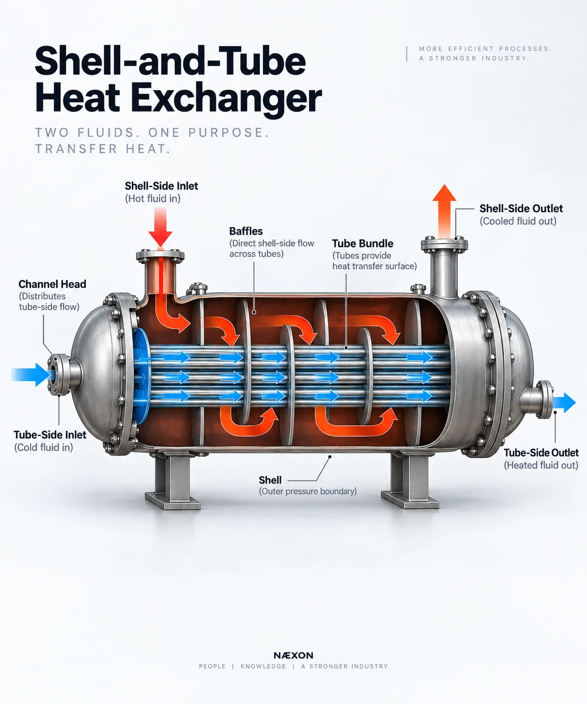
Figure: Cutaway view of a shell-and-tube heat exchanger showing hot shell-side flow across the tube bundle and cold tube-side flow through the tubes, allowing heat to transfer while keeping the two fluids physically separated.
A heat exchanger is equipment designed to transfer thermal energy from one fluid to another.
One fluid is hotter.
One fluid is colder.
A metal barrier separates them while allowing heat to pass through.
The fundamental idea is:
Hot fluid → Heat → Metal surface → Heat → Cold fluid
The two process streams normally remain physically separated.
This allows a refinery to recover energy that would otherwise be lost.
Why Refineries Use Heat Exchangers
Heat exchangers can perform several different jobs.
They may:
- Heat a process stream.
- Cool a process stream.
- Condense vapor into liquid.
- Vaporize liquid.
- Recover waste heat.
- Preheat feed before a furnace.
- Cool products before storage.
- Control equipment temperatures.
- Reduce furnace fuel consumption.
- Improve overall refinery energy efficiency.
A single refinery can contain hundreds or even thousands of heat-transfer devices.
The Shell-and-Tube Heat Exchanger
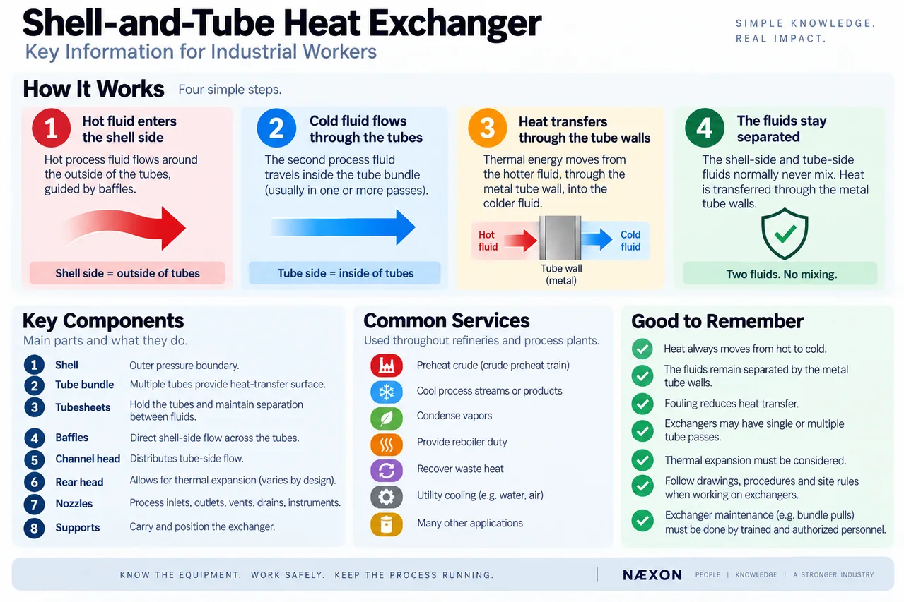
Figure: Quick-reference guide to shell-and-tube heat exchangers, showing how heat transfers between separate shell-side and tube-side fluids, along with the major components, common refinery services, and key operating principles.
The most recognizable refinery exchanger is the shell-and-tube heat exchanger.
Imagine a large cylindrical pressure vessel.
Inside it is a bundle containing many smaller tubes.
One fluid travels through those tubes.
Another fluid travels around the outside of the tubes but remains inside the larger shell.
The tube walls separate the two fluids.
Heat passes through those walls.
This creates two distinct flow paths:
Tube side
and
Shell side
Understanding those two terms is fundamental to exchanger work.
Major Components
A typical shell-and-tube exchanger can contain several major components.
Shell
The shell is the large cylindrical outer pressure boundary.
Shell-side fluid flows inside this vessel around the outside surfaces of the tubes.
Large process nozzles connect the shell to the refinery piping system.
Tube Bundle
Inside the shell is the tube bundle.
The bundle may contain hundreds or thousands of relatively small tubes.
These tubes provide enormous heat-transfer surface area.
The more effective surface area available, the more opportunity there is for heat to transfer between the two fluids.
Tubesheets
The ends of the tubes are secured into thick plates called tubesheets.
Each tube passes through a precisely located hole.
The tube-to-tubesheet connection helps maintain separation between the shell-side and tube-side fluids.
Depending on design, tubes may be expanded, welded, or connected using another engineered method.
Tube-to-tubesheet integrity is extremely important.
A leak here can allow the two process streams to communicate.
Channel Head
At one end of many exchangers is a channel head or stationary head.
This distributes tube-side fluid into the tubes.
Depending on exchanger design, internal partitions may divide the flow into multiple passes.
The large bolted joint between the channel and tubesheet is a familiar sight during refinery maintenance.
Bonnet
Some exchanger configurations use a bonnet instead of a removable channel cover arrangement.
Its purpose is still associated with directing tube-side flow.
The exact configuration depends on the exchanger design.
Baffles
Inside the shell, plates called baffles may be installed around the tube bundle.
Baffles serve important purposes.
They can:
- Direct shell-side fluid across the tubes.
- Increase fluid velocity.
- Improve heat transfer.
- Support the tubes.
- Reduce excessive tube movement.
Without appropriate flow direction, shell-side fluid could simply travel through the easiest path and bypass much of the useful heat-transfer surface.
Baffles force the fluid to interact more effectively with the tube bundle.
Tie Rods and Spacers
Baffles need to remain correctly positioned.
Tie rods and spacers can help maintain their spacing and provide structural support within the bundle.
These components may become particularly visible when a bundle is removed during a turnaround.
How Heat Actually Moves
Suppose hot oil flows through the shell while cooler crude oil travels through the tubes.
The hot oil transfers energy to the outside surface of the tube.
Heat conducts through the tube wall.
The cooler crude absorbs that heat from the inside surface.
The fluids never need to touch each other.
Yet energy moves from one stream to the other.
The hot stream cools.
The cold stream heats.
That is the basic principle behind enormous portions of refinery heat integration.
Countercurrent Flow
Many heat exchangers are arranged so the two fluids generally move in opposite directions.
This is called countercurrent flow.
Conceptually:
Hot fluid → → →
← ← ← Cold fluid
Countercurrent arrangements can maintain a useful temperature difference over much of the exchanger length and often provide efficient heat transfer.
Actual shell-and-tube flow patterns can be more complicated because of multiple passes and baffle arrangements.
Tube Passes
Tube-side fluid does not necessarily travel straight through once.
Internal partitions can redirect it.
For example, in a two-pass arrangement:
Fluid enters → travels through part of the tubes → turns around → travels back through another group of tubes → exits
Multiple passes increase velocity and influence heat-transfer performance and pressure drop.
This is why channel-head partition plates and the correct gasket arrangement matter.
Exchanger Nozzles
From a pipefitter’s perspective, exchangers often have four major process connections:
- Tube-side inlet
- Tube-side outlet
- Shell-side inlet
- Shell-side outlet
Additional connections may include:
- Vents
- Drains
- Instrument connections
- Relief connections
- Chemical-cleaning connections
- Utility connections
Never determine the service of a nozzle solely from its location.
Use the approved P&ID, exchanger drawings, line numbers, and project documentation.
Why Some Exchangers Are Stacked
Refinery exchangers are frequently installed in horizontal stacks.
You may see two or more exchangers mounted one above another.
Stacking can reduce plot-space requirements and support process arrangements where several exchangers operate together.
For maintenance crews, however, stacked exchangers can complicate:
- Rigging
- Blind installation
- Channel removal
- Bundle pulling
- Scaffold access
- Bolt removal
- Flange alignment
- Hydrotesting
This is why exchanger work can become a major turnaround activity.
Fixed-Tubesheet Exchangers
In a fixed-tubesheet exchanger, the tubesheets are attached to the shell.
This creates a mechanically straightforward arrangement.
However, thermal expansion between the shell and tubes must be considered.
Cleaning access can also differ from designs with removable bundles.
Floating-Head Exchangers
A floating-head exchanger allows one end of the tube bundle to move relative to the shell.
This accommodates differential thermal expansion between the shell and tubes.
It can also permit bundle removal for inspection and cleaning.
These exchangers can contain considerably more internal hardware than they appear to from the outside.
U-Tube Exchangers
A U-tube exchanger contains tubes bent into a U shape.
Both tube ends terminate at the same tubesheet.
The bends allow the tubes to expand and contract more freely.
The bundle can often be removed from the shell.
However, mechanically cleaning the inside of the tight U-bend portion can be more difficult than cleaning straight tubes.
What Is a Bundle Pull?
During a turnaround, one of the most recognizable exchanger maintenance activities is pulling the bundle.
The exchanger is properly shut down, isolated, drained, prepared, opened, and made ready according to the site’s procedures.
The tube bundle is then extracted from the shell using engineered pulling and rigging equipment.
Once removed, crews can inspect areas that are normally inaccessible.
A pulled exchanger bundle is one of the best opportunities for tradespeople to understand how the equipment actually works.
What Workers Inspect
Once an exchanger is opened, inspection may focus on:
- Tube condition
- Tubesheet condition
- Tube-to-tubesheet joints
- Baffles
- Shell interior
- Channel
- Pass partitions
- Gasket surfaces
- Corrosion
- Erosion
- Fouling
- Deposits
- Cracking
- Mechanical damage
Inspection requirements depend on the exchanger’s service, metallurgy, history, and applicable procedures.
Fouling
One of the biggest enemies of heat exchangers is fouling.
Deposits build on heat-transfer surfaces.
They may form inside tubes or on their external surfaces.
Possible deposits can include:
- Coke-like material
- Corrosion products
- Scale
- Salts
- Sediment
- Process contaminants
Deposits create an insulating layer.
Heat now has to travel through:
Fluid → Deposit → Metal → Deposit → Fluid
Heat transfer becomes less effective.
What Fouling Does to Performance
As fouling increases, several things may happen.
The exchanger may:
- Transfer less heat.
- Develop increased pressure drop.
- Require greater pumping effort.
- Restrict process flow.
- Cause downstream temperature problems.
- Increase furnace duty elsewhere in the unit.
- Reduce overall process capacity.
A piece of equipment can therefore look completely normal externally while becoming progressively less effective internally.
Tube Plugging
Individual tubes can become damaged.
Depending on the approved repair strategy, damaged tubes may sometimes be isolated using engineered tube plugs.
Plugging prevents process fluid from passing through the affected tube.
But plugging too many tubes reduces available heat-transfer area and changes flow characteristics.
Tube plugging is therefore not something performed arbitrarily.
It is controlled by engineering and inspection requirements.
Tube Leaks
A tube leak can allow shell-side and tube-side fluids to communicate.
Depending on the service, this can range from an efficiency problem to a serious process hazard.
Possible indications may include unexpected:
- Pressure behavior
- Product contamination
- Level changes
- Temperature changes
- Process composition changes
- Utility contamination
The consequences depend heavily on which fluid is at higher pressure and what materials are involved.
Thermal Expansion
Heat exchangers routinely experience significant temperature changes.
Metal expands as it heats.
It contracts as it cools.
The shell and tubes may not expand by exactly the same amount.
Exchanger designs therefore have to accommodate differential thermal expansion.
This is one reason floating-head and U-tube designs exist.
Thermal movement also matters to the piping connected to the exchanger.
Why Piping Stress Matters
Large exchanger nozzles are not designed to act as anchors for poorly aligned piping.
Excessive piping loads can place unwanted forces and moments on equipment nozzles.
During installation and maintenance, workers should never assume bolts should simply be used to pull severe misalignment into place.
Alignment problems should be addressed according to the applicable engineering and site procedures.
Good pipefitting protects the equipment as well as the pipe.
Gasket Surfaces Matter
Exchanger maintenance often involves large bolted flanges.
These joints may experience significant temperature and pressure cycles.
Before closure, flange faces and gasket seating surfaces must meet the applicable requirements.
Problems can include:
- Scratches
- Pitting
- Corrosion
- Residual gasket material
- Mechanical damage
- Incorrect gasket installation
- Misalignment
A leak at a large exchanger channel or shell flange can create a significant startup problem.
Bolt-Up Matters
Large exchanger flanges can contain dozens of studs.
Proper tightening is not simply a matter of making every nut “really tight.”
Approved procedures may specify:
- Bolt condition
- Lubrication
- Tightening sequence
- Multiple passes
- Torque
- Tensioning
- Final verification
The objective is controlled gasket compression and reliable joint integrity.
Hydrotesting
After certain maintenance activities, an exchanger may require pressure testing according to the approved inspection and repair plan.
Different test arrangements can help evaluate different pressure boundaries.
For example, testing may be used to investigate the integrity of:
- Tubes
- Tubesheets
- Shell
- Channel
- Flanged joints
The exact testing method and pressure must come from approved engineering and inspection requirements—not field assumptions.
Air-Cooled Heat Exchangers
Not every refinery exchanger uses another process liquid.
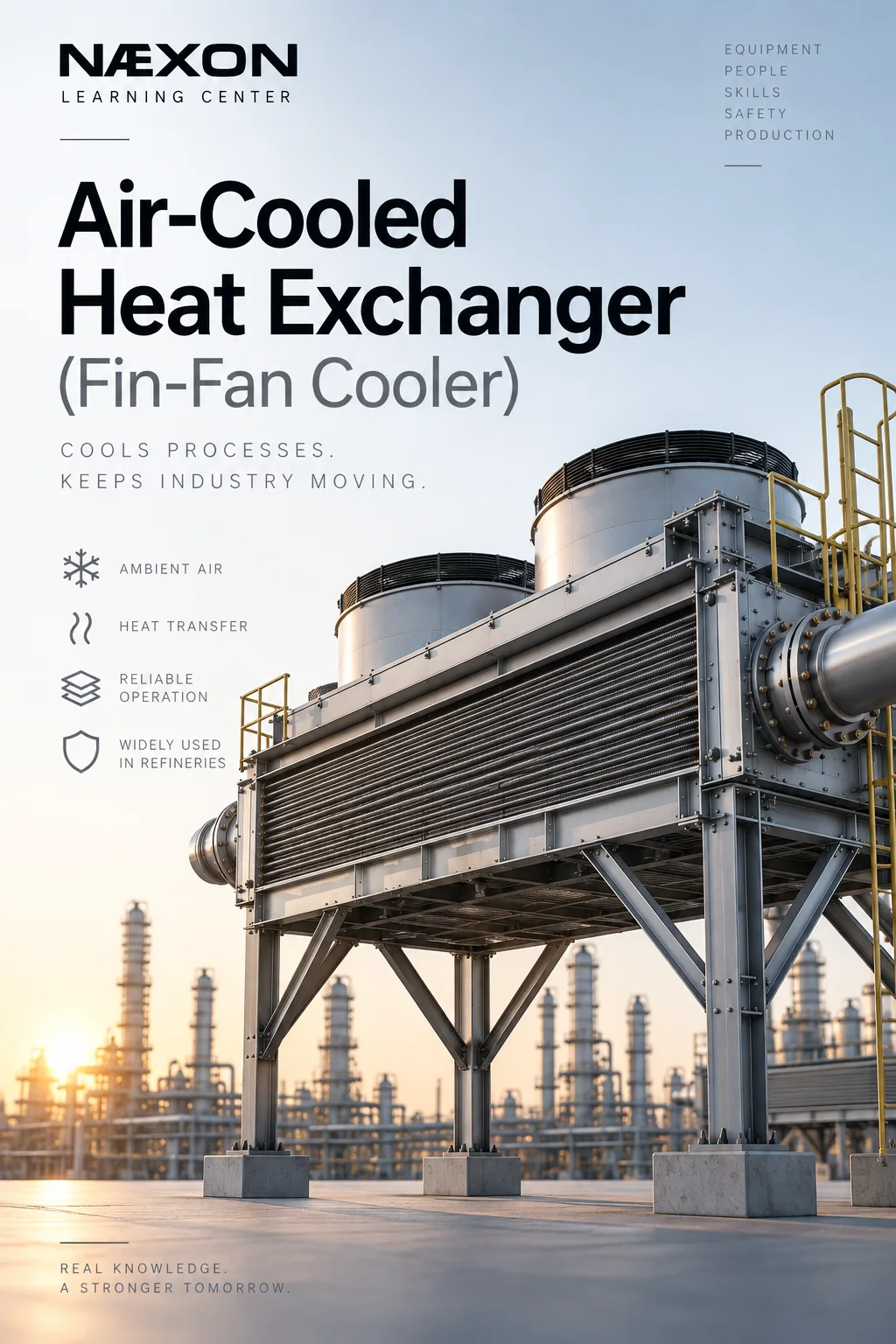
Refineries also commonly use air-cooled heat exchangers, often called air coolers or fin-fans.
Process fluid flows through finned tubes while large fans move atmospheric air across them.
Heat transfers:
Hot process fluid → tube wall/fins → air
These units are commonly seen elevated on structural steel with large fans beneath or above the tube bundles.
Reboilers
A reboiler is a specialized heat exchanger used to provide heat to a distillation system.
Liquid from the lower portion of a tower is heated so that part of it vaporizes.
The generated vapor returns to the tower and helps drive separation.
This directly connects heat-exchanger operation to the distillation-tower process we have already studied.
Condensers
A condenser removes heat from vapor until some or all of that vapor becomes liquid.
Distillation tower overhead systems frequently use condensers.
The basic sequence can be:
Tower vapor → condenser → condensed liquid → receiver
Some of that liquid may then return to the tower as reflux.
Exchangers and the Crude Preheat Train
One of the best refinery examples of energy recovery is the crude preheat train.
Hot refinery streams leaving various parts of the crude unit contain valuable thermal energy.
Instead of throwing that heat away, exchangers transfer it into the incoming crude.
The crude becomes progressively hotter before reaching the fired heater.
This means the furnace needs less fuel to reach the required outlet temperature.
The refinery effectively recycles heat.
Common Exchanger Problems
Field personnel may encounter exchanger work associated with:
- Fouled tubes
- Plugged tubes
- Tube leaks
- Tube vibration
- Corrosion
- Erosion
- Gasket leaks
- Flange leaks
- Damaged pass partitions
- Tubesheet damage
- Baffle damage
- Shell corrosion
- Nozzle damage
- Excessive pressure drop
- Poor heat transfer
- Piping alignment problems
Some problems are mechanical.
Some are process-related.
Many involve both.
What Operators Watch
Operators may monitor exchanger performance through parameters such as:
- Inlet temperature
- Outlet temperature
- Flow
- Pressure
- Differential pressure
- Downstream process behavior
A gradual loss in thermal performance can indicate fouling.
Increasing pressure drop may indicate restriction.
Unexpected process contamination may indicate leakage between the two sides.
These observations help determine when inspection or cleaning may be required.
Turnaround Field Knowledge
When exchanger work begins during a shutdown, good field organization becomes extremely important.
Crews may need to manage:
- Blinds
- Flange locations
- Gaskets
- Studs
- Channel covers
- Bundle components
- Internal partitions
- Inspection holds
- Cleaning
- Testing
- Reassembly
Parts that look interchangeable may not actually be interchangeable.
Marking orientation and component location according to the work package can prevent expensive reassembly mistakes.
Important Terminology
Shell — Outer pressure-containing body of a shell-and-tube exchanger.
Tube — Small-diameter flow passage providing heat-transfer surface.
Tube bundle — Assembly containing the exchanger tubes and supporting internals.
Tubesheet — Thick plate securing and separating the tube ends.
Tube side — Fluid flowing through the tubes.
Shell side — Fluid flowing around the tubes inside the shell.
Baffle — Internal plate used to support tubes and influence shell-side flow.
Channel — Exchanger head that distributes tube-side fluid.
Pass partition — Internal plate directing tube-side fluid through designated tube passes.
Fouling — Accumulation of deposits on heat-transfer surfaces.
Bundle pull — Removal of a removable tube bundle from the exchanger shell.
Reboiler — Heat exchanger used to generate vapor for a distillation system.
Condenser — Heat exchanger used to convert vapor into liquid by removing heat.
What Every Pipefitter Should Know
When you walk up to a shell-and-tube exchanger, develop the habit of asking:
- Which nozzles are shell side?
- Which are tube side?
- Which stream is hotter?
- Which stream is colder?
- What direction does each stream travel?
- Is the exchanger single-pass or multipass?
- Is the bundle removable?
- Where would the channel partitions be?
- Where are the vents and drains?
- How will thermal movement affect the connected piping?
- What must be removed if the bundle needs to be pulled?
Those questions transform an exchanger from “a vessel with four pipes” into a process system you can understand.
Field Rules
When working on refinery heat exchangers:
- Verify shell-side and tube-side services from approved documentation.
- Never assume a nozzle’s service based solely on physical location.
- Follow approved isolation and line-opening procedures.
- Treat exchanger contents as hazardous until the equipment has been properly prepared and released for work.
- Protect flange and gasket seating surfaces during maintenance.
- Keep foreign material out of open channels, shells, and tubes.
- Maintain the required orientation of pass partitions and internal components.
- Never modify, plug, weld, or alter tubes or internals without approved direction.
- Do not use flange bolts to force severe piping misalignment into place.
- Follow the specified bolting and gasket procedures during reassembly.
- Respect inspection hold points before closing equipment.
- Follow the approved testing procedure before returning equipment to service.
Knowledge Check
- What is the basic purpose of a heat exchanger?
- What is the difference between the shell side and tube side?
- What does a tubesheet do?
- Why are baffles installed?
- What is countercurrent flow?
- Why might an exchanger use multiple tube passes?
- What is fouling?
- How can fouling affect both heat transfer and pressure drop?
- What can happen when an exchanger tube leaks?
- Why are floating-head and U-tube designs useful for thermal expansion?
- What is a bundle pull?
- What is the difference between a condenser and a reboiler?
Practical Field Exercise
Find a shell-and-tube exchanger on an approved refinery P&ID.
Identify the four major process connections:
- Shell-side inlet
- Shell-side outlet
- Tube-side inlet
- Tube-side outlet
Determine which stream is hotter and which is colder.
Then sketch the exchanger.
Draw one stream through the tubes and the other through the shell.
Add arrows showing the direction of heat transfer.
Finally, locate the actual exchanger in the field if your work assignment and site rules allow it.
Compare the drawing with the physical equipment.
Identify the channel, shell, nozzles, flanges, vents, drains, supports, and connected piping.
That exercise connects three things every industrial craft worker should learn to combine:
The drawing. The equipment. The process.
Final Takeaway
A refinery heat exchanger is fundamentally an energy-transfer machine.
One fluid carries heat.
Another fluid needs that heat—or needs to carry it away.
The exchanger places those fluids extremely close together while keeping them separated by engineered metal surfaces.
Inside a shell-and-tube exchanger, tubes, tubesheets, baffles, channels, partitions, supports, and pressure boundaries work together to control that transfer.
Once you understand shell side, tube side, flow direction, temperature direction, and heat transfer, the complicated piping surrounding an exchanger starts making sense.
And that is one of the most useful transitions a refinery worker can make:
Stop seeing individual pieces of equipment and start seeing how energy and process material move through the entire unit.